16
Rev. C • 10.2004
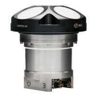
End bell with connector
External
view
AB
CDEF
GH J K
LM
1
2
3
4
5
6
7
8
9
10
11
12
Pin No. Function
1AAnalogue out 1
2BAnalogue out 2
3CAnalogue out 3
4DAnalogue out 4
5EGnd
6FSynchIn
7GSynchOut
8HGnd
9JTx
10 K Rx
11 L Gnd (Power –)
12 M Power + (12–48 V)
IP68 connector
(external view)
Impulse connector
(external view)
The two connectors available
for the Vectrino and the
corresponding pin-outs.
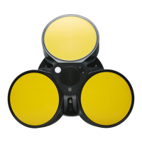
The probe consists of four receive transducers, each mounted inside a receiver
arm, and a transmit transducer in the centre. The trans ducers are each covered
with a hard epoxy and the probe is other wise titanium.
Temperature Sensors
The temperature sensor is located inside the probe head.
Electronics Module
The electronics module is located inside the pressure case, and is a single board
that holds the power transmitter, analogue and digital sig nal processing, power
conditioning and the standard data recorder.
Power & Communication Cable
The power and communication cable is connected to the end bell con nector. The
cable supplies external DC power (12–48 V), connects an external computer to
the Vectrino for 2-way serial communication, for analogue output of the three
velocity components, and furthermore it provides synchronization options (Vec-
trino can be used both as master and as slave to synchronize measurements with
other Vectrinos and/or other transducers).
Cable Wiring. The Vectrino comes standard with a 12-conductor connector and
cable. The connector type is either IP68 connector or MCBH-12-FS, bronze
(Impulse). The Vectrino power lines are diode protected, so you don’t have to
worry about wiring the Vectrino power backwards – this will not damage your
instrument. The pin-out is shown in the side bar.
Functional Description
This section briefl y describes some of the underlying principles that control the
operation and application of the Vectrino Velocimeter.
The Vectrino has two modes of operation:
• Command mode.
A Vectrino in command mode is ready to accept your in-
structions.
• Data Acquisition Mode. The Vectrino enters data acquisition mode when you
click any of the Start commands (e.g. Start Data Collection) in the Vectrino
software. The Vectrino collects data without breaks.
CHAPTER 3
Technical Description