EasyManua.ls Logo

Nortrac 82XTC - Page 52

Nortrac 82XTC
117 pages
Print Icon
To Next Page IconTo Next Page
To Previous Page IconTo Previous Page
Loading...
Operation Instruction
46
2.17.11 Central Electrical Box
The circuit control elements include the power supply relay,
electronic flasher, lighting relay and fifteen-fuses.
The operating current of each gear and the electrical devices
under its protection are shown in Table 2-3. When an
electrical element is broken, check the fuse. If damaged,
take down a standby fuse with of the same rating from
the circuit board and replace it to protect the electrical elements
from damage.
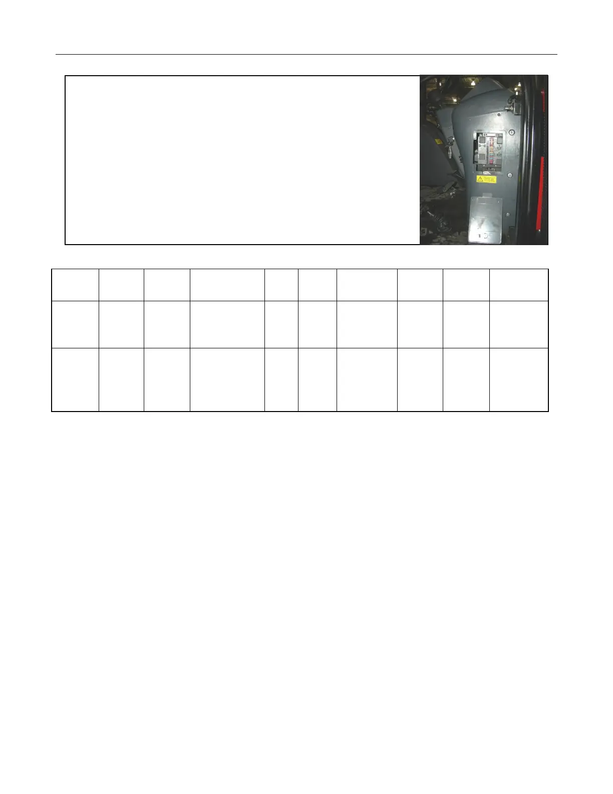
Figure 2-56 Central Electric Box
Table 2-3 Operating Current of Each Gear of the Fuse Box and the Electrical Devices
Gear of
Fuse Box
One
Two
Three
Four
Five
Six
Seven
Eight
Nine
Rated
Operating
Current
10A
10A
20A
10A
10A
20A
5A
20A
15A
Protected
Electric
Device
Braking
lamp and
horn
Turn
light and
warning
device
Wiper and
air-conditioner
Low
beam
High
beam
Power
accessories
Position
lamp
Top
light
Lighting
relay

Table of Contents

Related product manuals