Maintenance Instructions
4.11.5 Headlight Illumination Intensity Distribution
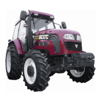
As Figure 4-16 shows, the curve of the illlumination intensity distribution
is applicable to right-side traveling. If necessary, check and adjust the
illumination intensity distribution for the headlilghts. Figure 4-16
Head Lamp Illumination
The procedure is as follows: Intensity Distribution
1. Check the tire pressure and make sure that it meet the requirements.
2. Place the (empty-load) tractor on a level plane, facing a smooth wall.
3. Place two “+” signs on the wall corresponding to head lamp central line.
● Turn on the low beam light switch when the tractor is at distance of 5m from the wall.
● The reference point (P-P) is located at 5cm under the “Cross” mark on the wall.
● Turn the adjusting nut of the headlight to regulate its distribution curve.
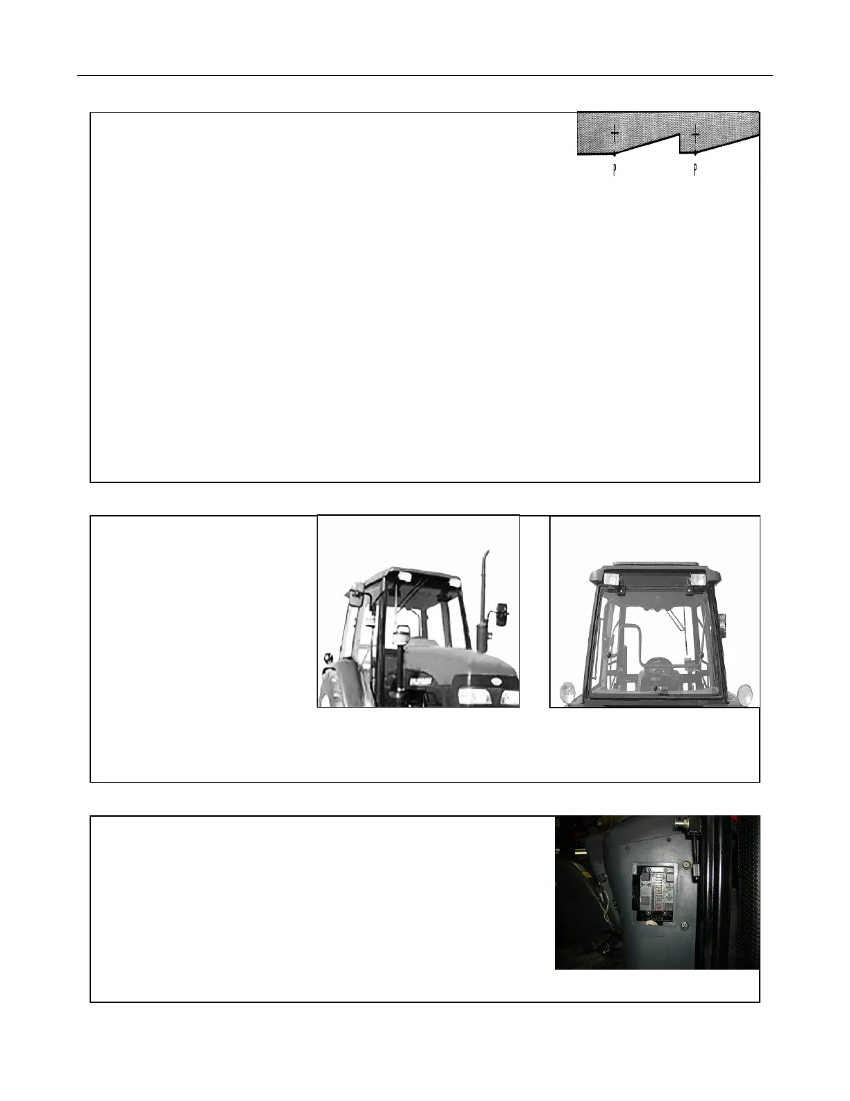
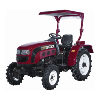
4.11.6 Top Lights
There are four top lights on the
cab, which are located on the front
upper and rear upper parts of
the cab.
The cab front top lights are shown
in Figure 4-17; the cab rear top
lights are shown as Figure 4-18.
Figure 4-17 Front Top Lights Figure 4-18 Rear Top Light
It is possible to turn on the left and right top lights according to the requirement of work.
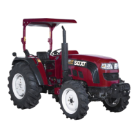
4.11.7 Fuse Box
There are strip fuses in the fuse box.
The working current for each circuit and its protected electric
devices are shown in Table 4-2. When there are electric problems,
First check the fuse box.
If the fuse is broken, take a replacement fuse from the
circuit board (brass wire replacement not allowed) and replace
it in order to ensure the safety of the electric element.
Fig.4-19 Fuse Box