When the control handle is pushed from the N position to the front
position, the suspension system will start to rise. When reaching the
deadline position, the control handle will move back automatically
(i.e. back to the N position).
When the control handle is pushed from the N position to the reverse
direction (at such time, the control lever is not in the rear position,
the suspension system will descend. Once you release the control handle,
it will go back to the N position, the descent will stop.
When the control handle is pushed from the N position to the lowest
position, the suspension system stays in the “floating” state after
dropping down to the final position.
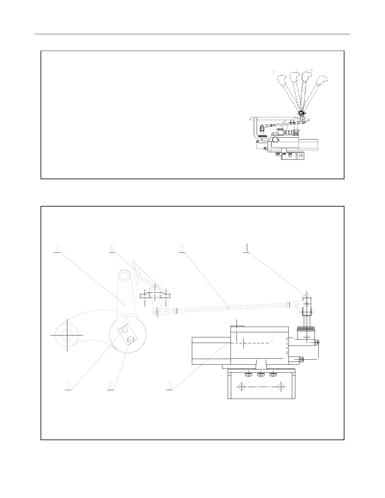
Figure 4-22 Hydraulic System Use
You can control the lift height of farm implements by adjusting the position of the limitor (see adjustment
procedure). Refer to the Figure 4-23 and make any adjustments as per the procedures described, to
prevent breakage of the PTO shaft caused by the farm implement being lifted too high.
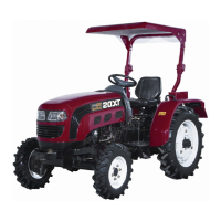
Fig 4-23 Lifter Height Limiter
1. Nuts (1) 2. Nuts (2) 3. Distributor 4. Control System
5. Feedback Lever 6. Height Limitor Feedback Lever Parts 7. Push Board