Applications Synchronization
28 ACPS-2406 PN 51304:B 09/02/2003
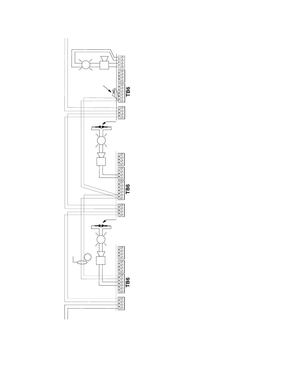
Refer to the following figures for application illustrations.
Figure 4.4 Supervised Master/Slave Synchronization Connections (Non-Coded)
TB5TB8
TB4
TB5TB8
TB4
TB5TB8
TB4
SLC from
FACP or
previous
Device on
SLC
ACPS-2406
ACPS-2406
ACPS-2406
SLC
To Next Device on
SLC
SLC
DIP Switch Settings*
2.3 OFF
3.3 OFF
2.5 ON
2.6 OFF
2.7 ON
2.4 OFF
3.4 OFF
DIP Switch Settings*
2.2 OFF
3.2 OFF
2.5 ON
2.6 OFF
2.7 ON
3.7 OFF
3.8 OFF
DIP Switch Settings*
2.1 OFF
3.1 OFF
2.5 ON
2.6 OFF
2.7 ON
3.7 OFF
3.8 OFF
* DIP Switches SW 2.8, 3.5, and 3.6 also require setting to determine AC and battery charger information. See Table 3.1
ACPS6app1.cdr
100 ohm maximum
loop resistance
P/N ELR-2.2K
(2.2K ohm end-of-
line resistor)
Note:
• Application drawing is typical for System Sensor SpectrAlert Series horns/strobes. This application may be
used for Gentex or Wheelock electronically synchronized devices by changing SW 2.6 and 2.7
• Do not “T-tap” synch riser.
• In this configuration the synchronizing wiring (A) must be connected to the power supplies within 20 feet (6.1 m) in
conduit.
P/N ELR-2.2K
(2.2K ohm end-of-
line resistor)
P/N R-2.2K
(2.2K ohm
end-of-line
resistor)
A