Synchronization Applications
ACPS-2406 PN 51304:B 09/02/2003 29
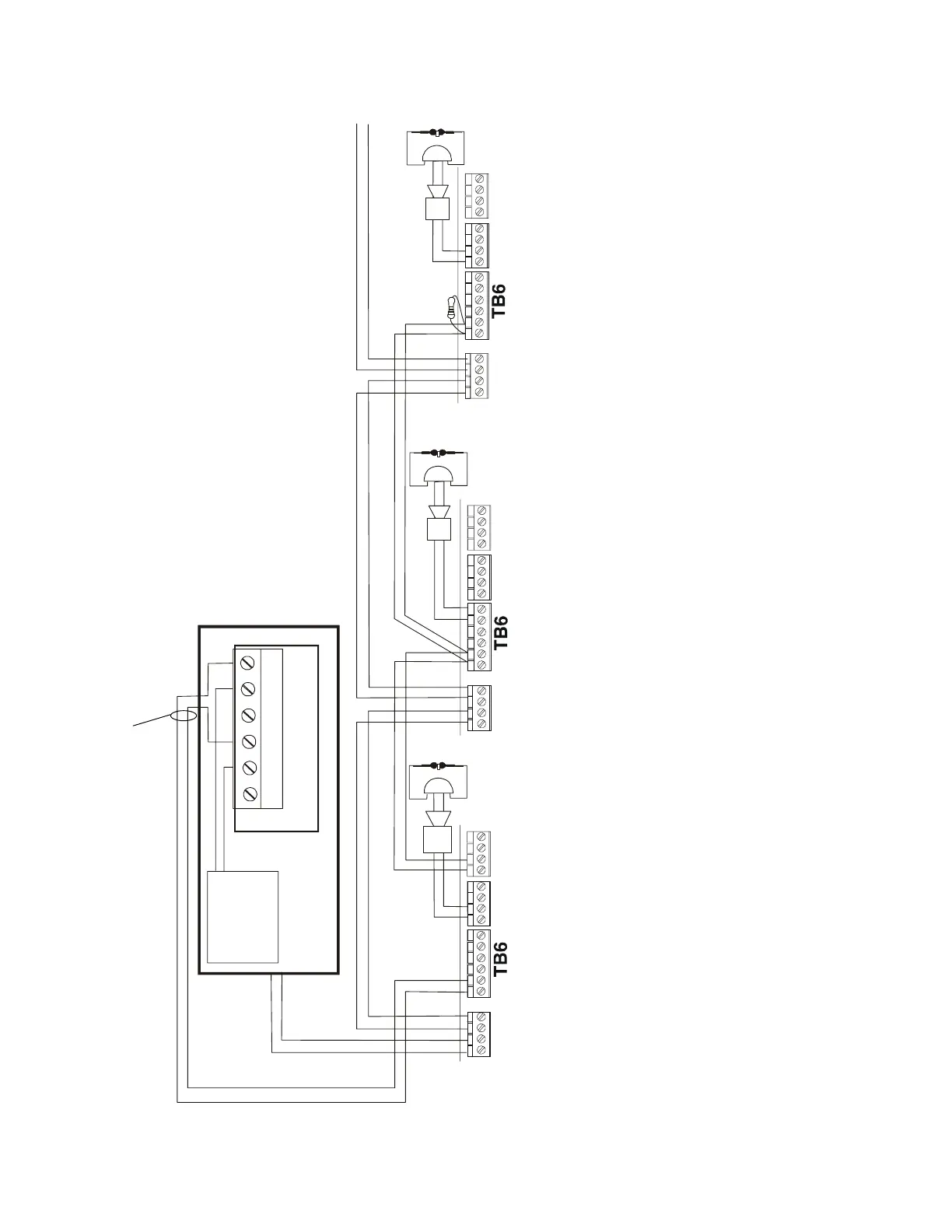
Figure 4.5 Supervised Synchronization Wiring Using UZC-256
TB5TB8
TB4
TB5TB8
TB4
TB5TB8
TB4
FACP
SLC
SLC to Next Device
UZC-256
NO
COM
NO
NC
NC
COM
SLC
24 Volt Synchronization Riser
ACPS-2406
ACPS-2406
ACPS-2406
-
P/N R-2.2K
(2.2 K ohm
end-of-line
resistor)
DIP Switch Settings*
3.7 OFF
3.8 ON
3.1 OFF
3.2 OFF
2.6 OFF
2.7 OFF
DIP Switch Settings*
3.7 OFF
3.8 ON
3.3 OFF
DIP Switch Settings*
3.7 OFF
3.8 ON
3.2 OFF
* DIP Switches 3.5, 3.6, and 2.8 also require setting to determine AC and battery charger information. See Table 3.1.
Note:
• Strobes or horn/strobes of any manufacturer may not be used on coded buses.
• No NAC devices may be on the synchronization riser. This riser must be in the same cabinet as the FACP or within 20 feet (6.1m) in conduit, or it must be supervised with an approved power
supervision relay.
• The UZC-256 is compatible with Notifier control panels except the AFP-100 and AFP-200. The UZC-256 must be mounted inside the FACP or in conduit within 20 feet (6.1 m) of the panel in the
same room.
-
+
-
+
P/N ELR-
2.2K (2.2 K
ohm end-
of-line
resistor)
SLC
+
-
+
-
+
-
-
+
+
P/N ELR-
2.2K (2.2 K
ohm end-
of-line
resistor)
P/N ELR-
2.2K (2.2 K
ohm end-
of-line
resistor)
+24V power
source
+
-
The wiring from the FACP shall be within 20 feet (6.1 m) in conduit
in the same room, or supervised with an approved power
supervision relay. See the UZC Installation Manual for more
information on the applications that require power supervision.
ALARM POLARITIES
SHOWN
-
+
-
+