AFP-200 Instruction PN 15511:F2 10/11/99 113
Appendix K UL Power-limited Wiring
Requirements
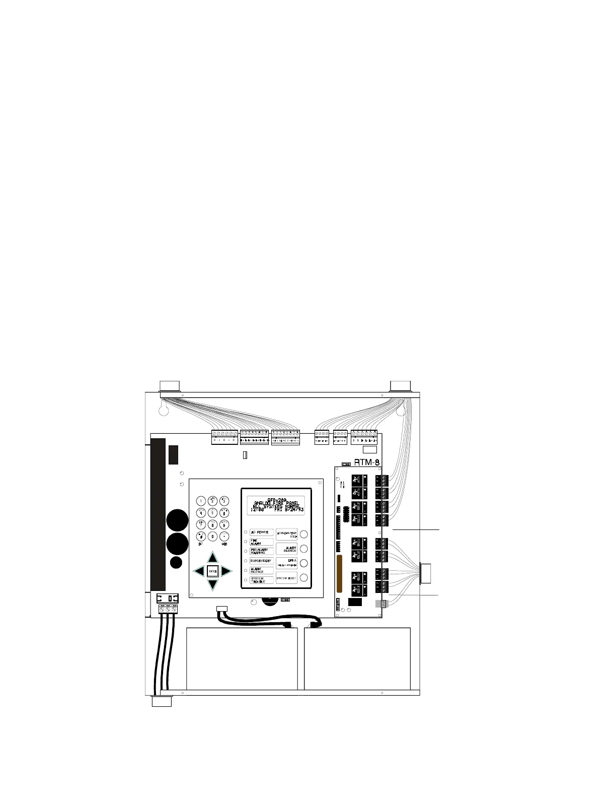
Figure K-1 Typical Wiring Diagram for UL Power-limited Requirements
AC Power
0.25" gap
0.75" gap
Nonpower-limited Circuits
Power-limited Circuits
Power-limited Circuits
General Description
Power-limited and nonpower-limited circuit wiring must remain separated in the cabinet. All power-limited
circuit wiring must remain at least ¼ inch away from any nonpower-limited circuit wiring. Furthermore, all
power-limited and nonpower-limited circuit wiring must enter and exit the cabinet through different knockouts
and/or conduits. A typical wiring diagram for the AFP-200 is shown in Figure K-1.
RTM-8 Relay Transmitter Module
Refer to Figure 2-35 for additional information on this module. Figure K-1 below shows the RTM-8 Module
installed in the AFP-200. Power-limited and nonpower-limited wiring must maintain a minimum distance of ¼
inch wire to wire. Note that a gap of ¾ inch exists between relay four and relay five. It is recommended that if
using this module to drive both power-limited and nonpower-limited circuits, use the first four relays to drive
power-limited circuits and the next four relays to drive nonpower-limited circuits. Using relays 5-8 for non-
power-limited circuits allows grouping them with the transmitter output nonpower-limited wiring.
If using all relays as power-limited circuits, the .25 inch gap between relay eight and the nonpower-limited
transmitter output terminal meets UL power-limited wiring requirements.