112 AFP-200 Instruction PN 15511:F2 10/11/99
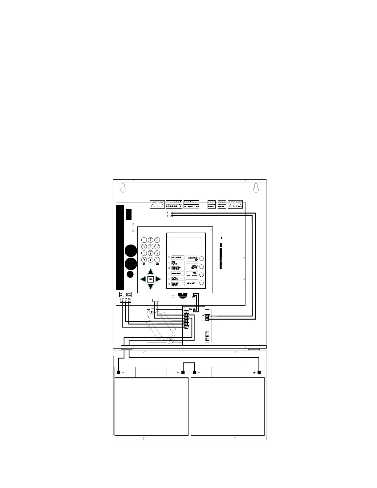
3. Connect AVPS-24/AVPS-24E output to control panel Notification Appliance Circuits 3 and 4 as follows:
Cut jumpers JP6 and 7, located in the top center of the control panel circuit board.
Plug the bell power cable, PN 71093 into plug J10. Plug J10 is located in the top center of the control panel
circuit board.
Connect J10 (–) to TB2 terminal 2 on the AVPS-24/AVPS-24E.
Connect J10 (+) to TB2 terminal 1 on the AVPS-24/AVPS-24E.
4. Connect the AVPS-24/AVPS-24E trouble output to the control panel as follows:
Cut jumper JP3, located in the bottom right center of the control panel circuit board.
Plug the gray trouble cable, PN 71033 into Plug J11 with the wires exiting the connector on top. Plug J11 is
located in the bottom right center of the control panel circuit board.
Plug the other end of the cable into P1 with the wires exiting from the bottom.
5. Primary power is connected to the AVPS-24/AVPS-24E as follows:
Connect earth ground to TB1 terminal 6, connect AC hot to TB1 terminal 5, and connect AC neutral to TB1
terminal 4.
6. Battery Connections:
Connect the battery (–) to AVPS-24/AVPS-24E TB1 terminal 3. Connect the battery (+) to AVPS-24/
AVPS-24E TB1 terminal 2.
Figure J-1 AFP-200/AVPS-24 Power Expansion
PN 71033
PN 75203
PN 71093