AFP-200 Instruction PN 15511:F2 10/11/99 31
Operation
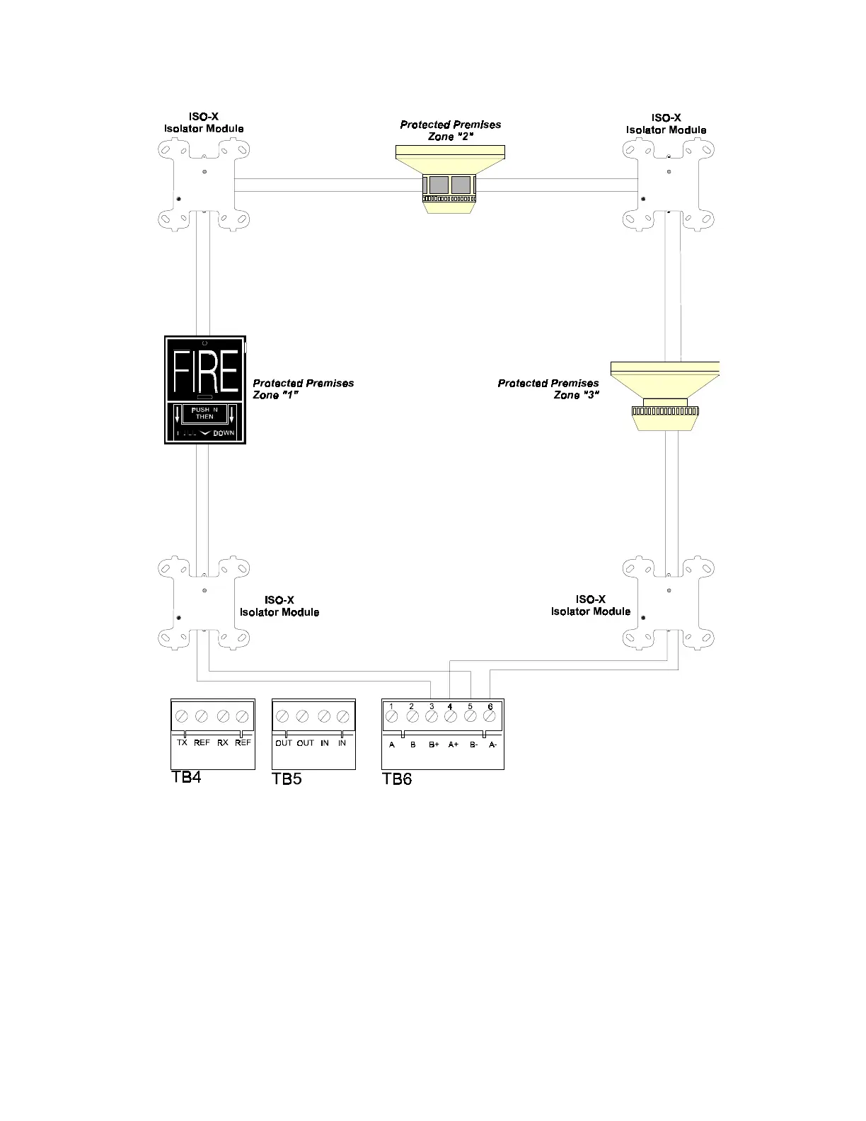
By “flanking” each communications loop device with a pair of ISO-X isolator modules, each device is protected
from short circuit faults that may occur on other devices. For example, a fault on Zone 2 will not affect Zones 1
and 3. The isolator modules on either side of Zone 2 will open the communications loop. Zone 1 will still
operate from power on loop out and Zone 3 will operate from loop return. Because the control panel will no
longer be able to communicate with Zone 2, a trouble signal(s) will be generated for that device.
No T–tapping or branching is allowed on this circuit. The ratings and characteristics are the same as for a four-
wire circuit meeting NFPA Style 6 requirements.
Figure 2-16 Four Wire SLC Communications Loop
(meets NFPA 72-1993 Style 7 requirements)
Connect Loop Out to TB 6-3 (+) and TB 6-5 ().
Connect Loop Return to TB 6-4 (+) and TB 6-6 ().
2.7 Wiring the Signaling Line Circuit, continued