32 AFP-200 Instruction PN 15511:F2 10/11/99
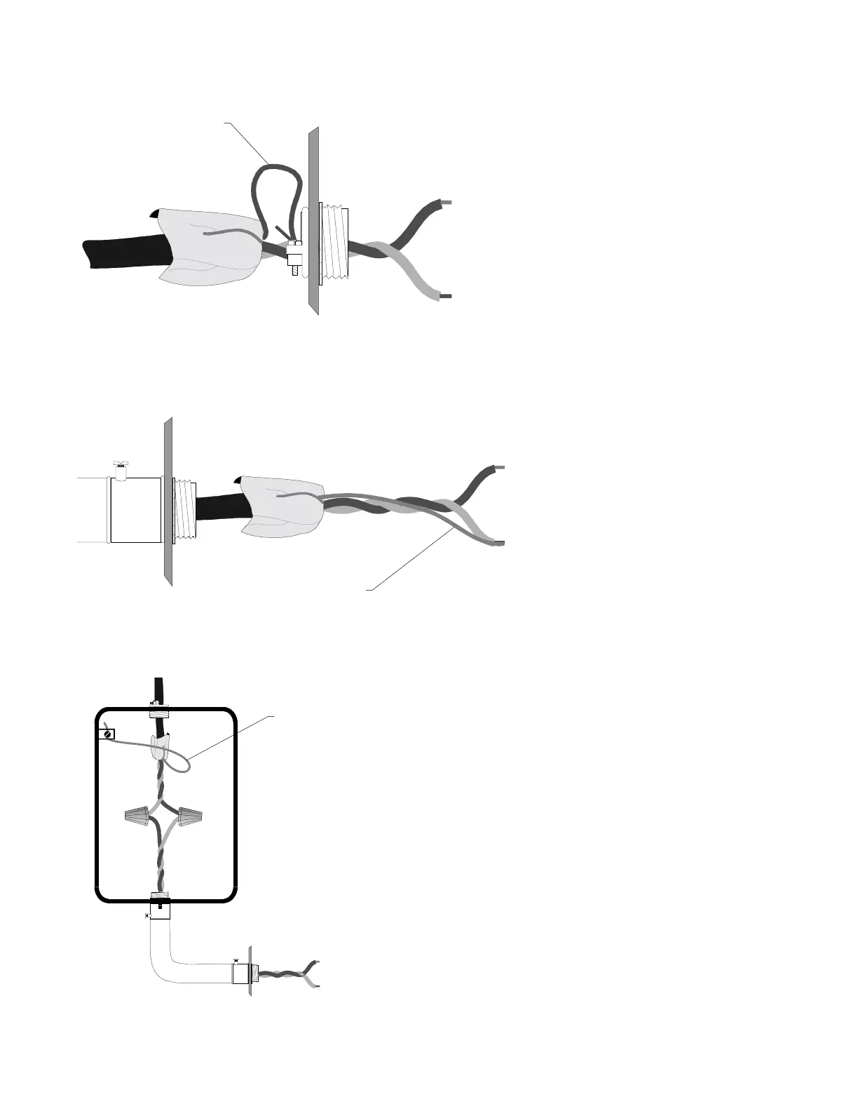
Figure 2-17 Shield Termination in No Conduit
Figure 2-18 Shield Termination in Full Conduit
Must employ metal conduit
and a metal box.
Cabinet
Cabinet
Loop +
Loop -
Shield Drain Wire The shield
must not be connected to earth
ground at any point.
Loop +
Loop -
Shield Drain Wire
Shield Drain Wire
Figure 2-19 Shield Termination in Partial Conduit
Do not allow the shield drain wire to enter the system
cabinet or the conduit. Connect the drain wire to the
termination point of the conduit run. Note: The conduit
cannot be longer than 20 feet.
The shield drain wire must be
connected to the negative () side of
the loop. Do not allow the shield
drain wire or the shield foil to touch
the system cabinet. Note: For Style 6
or Style 7 field wiring of the Commu-
nications Loop, connect each end of
the shield to the negative side of the
respective channel.
Do not allow the shield drain wire to enter
the system cabinet. Connect the drain wire
to the outside of the cabinet via a BX-type
connector. Note: scrape paint away from
cabinet to make good electrical connection.
Cabinet
2.7 Wiring the Signaling Line Circuit, continued