AFP-200 Instruction PN 15511:F2 10/11/99 39
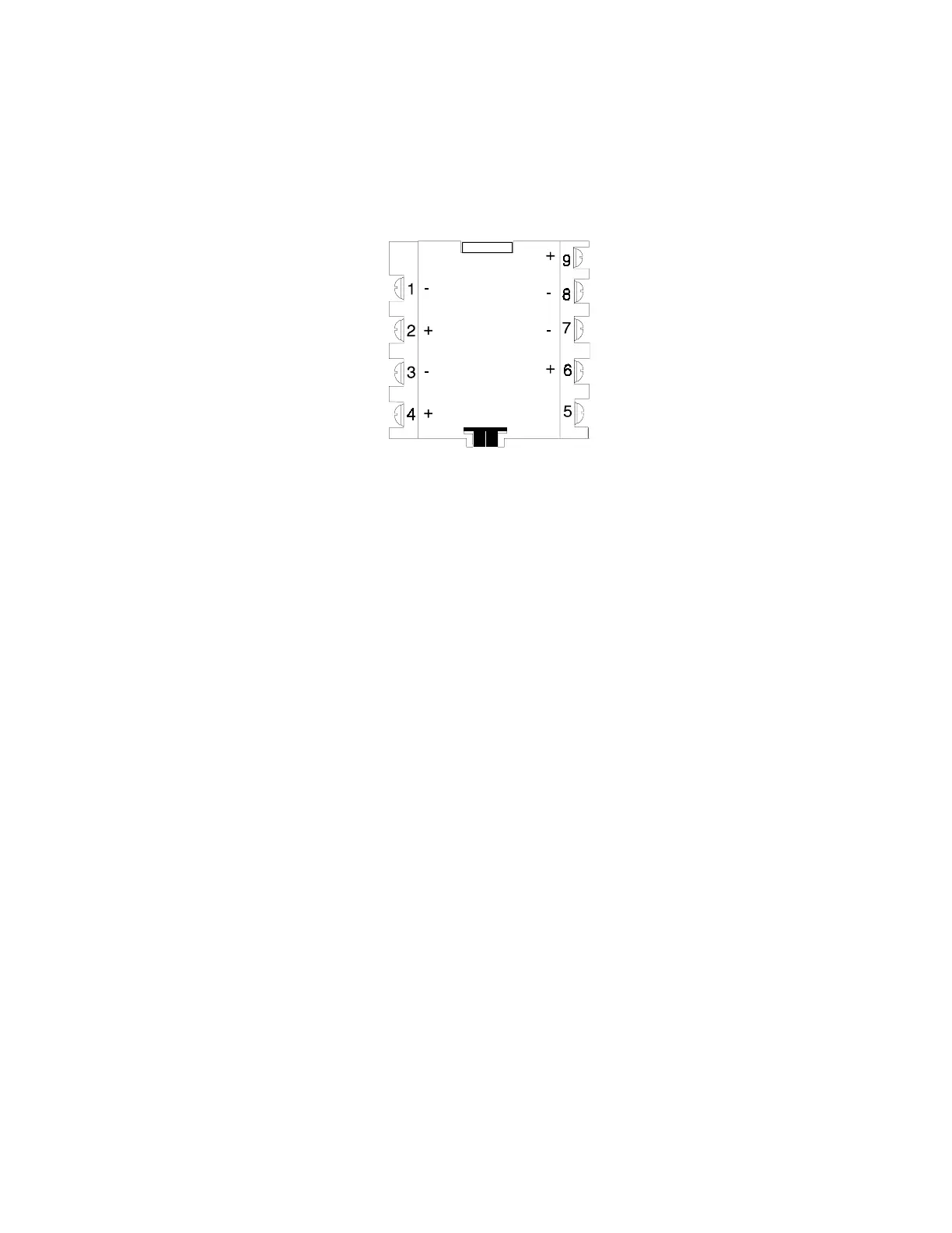
CMX
Style D NAC (+)
Loop (–) Style D NAC (–)
Loop (+) Style B NAC (–)
24 VDC Power (–) Style B NAC (+)
24 VDC Power (+)
Communications (SLC) Loop Connections
Connect the communications loop to CMX terminals 1 (–) and 2 (+). The CMX occupies one module address
on the loop. Set the rotary switches on the CMX to the particular loop address required.
NFPA Style Y Notification Appliance Circuit
Connect polarized alarm notification appliances to a single two-wire circuit. This circuit cannot be T-tapped or
branched in any fashion, and must be terminated across the last device by a 47K, 1/2-watt ELR (PN A2143-00).
Connect the circuit to CMX terminals 6 (+) and 7 (–). See Figure 2-28.
NFPA Style Z Notification Appliance Circuit
Connect polarized alarm notification appliances to a single two-wire circuit. This circuit cannot be T-tapped or
branched in any fashion. No external ELR is required for Style Z wiring. Connect the four-wire circuit to CMX
terminals 6 (+) and 9 (+), then 7 (–) and 8 (–). See Figure 2-29.
Notification Appliance Power
Connect notification appliance power to CMX terminal 3 (common) and terminal 4 (+ 24 VDC). This power
must be supervised by a UL-listed power supervision relay, wired as shown in Figure 2-28 and 2-29.
Test switch
The CMX includes a magnetic test switch located near the center front of the module. Activation of this switch
will cause a short circuit indication for the Style B/D loop.
2.7.3 The Control Module
The CMX control module is an addressable module that supervises and switches power to a Notification
Appliance Circuit. The CMX-1 and CMX-2 are identical except that the CMX-2 has a higher voltage rating
(70.7 V) at full current. The CMX circuit can be wired as an NFPA Style Y or Style Z Notification Appliance
Circuit. Alternately, the CMX can be used as a Form-C control relay.
Figure 2-26 The CMX Control Module (Alarm polarity shown)