EasyManuals Logo

Notifier AFP-200 User Manual

Notifier AFP-200
120 pages
To Next Page IconTo Next Page
To Previous Page IconTo Previous Page
Page #38 background imageLoading...
Page #38 background image
38 AFP-200 Instruction PN 15511:F2 10/11/99
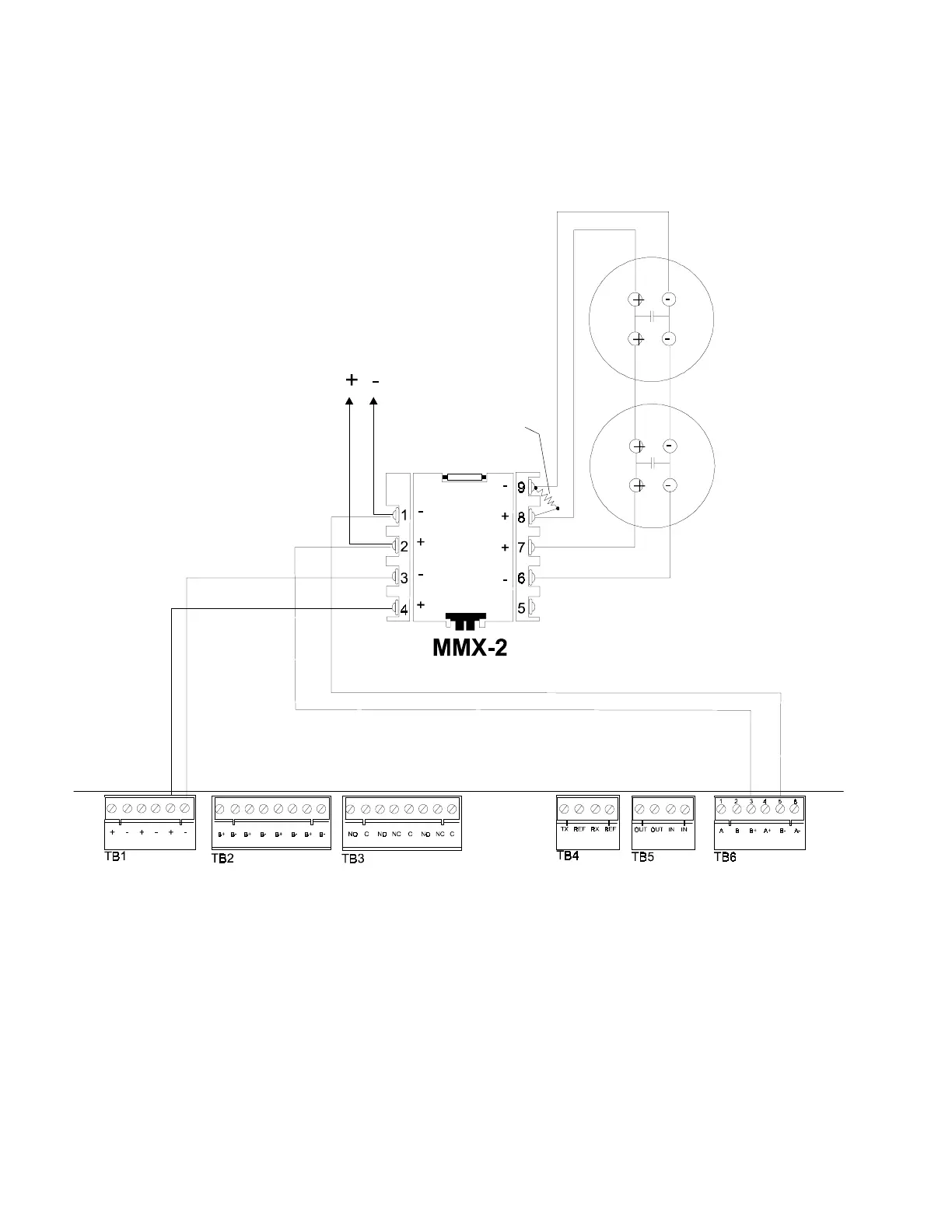
Figure 2-25 NFPA Style D Initiating Device Circuit
(supervised and power-limited)
24 V (+) TB1-5
24 V () TB 1-6
SLC (+) TB 6-3
SLC () TB 6-5
24 VDC
filtered,
regulated and
resettable
power
3.9K UL-listed ELR
To next
device on
Loop
Note: For more information, refer to the MMX-2 Installation Instructions, Document M500-03-00. For
compatible devices, reference the Device Compatibility Document.
Note: Maximum initiating device circuit
resistance is 25 ohms. Maximum alarm current
is 90 mA. Maximum detector standby current is
2.4 mA.
Compatible
Two-wire Smoke
Detectors
2.7.2 The Monitor Module, continued

Other manuals for Notifier AFP-200

Questions and Answers:

Question and Answer IconNeed help?

Do you have a question about the Notifier AFP-200 and is the answer not in the manual?

Notifier AFP-200 Specifications

General IconGeneral
Control Panel TypeAddressable Fire Alarm Control Panel
Auxiliary Power Output24 VDC, 500 mA
Operating Temperature32°F to 120°F (0°C to 49°C)
Display80-character LCD
Power Supply120 VAC, 60 Hz
Capacity198 addressable devices
Notification Appliance Circuits2
Relay Contacts3 (Form-C)
Relative Humidity93% non-condensing

Related product manuals