AFP-200 Instruction PN 15511:F2 10/11/99 87
Out (+)
EIA-485EIA-485
EIA-485EIA-485
EIA-485
ReturnReturn
ReturnReturn
Return
Shielded Twisted Pairs
EIA-485EIA-485
EIA-485EIA-485
EIA-485
OutOut
OutOut
Out
• Power-limited and supervised.
• Maximum of four LCD-80s may be
connected to this circuit when pow-
ered by the control panel.
• If LCD-80s are powered by a sepa-
rate UL-listed power supply, up to
32 may be connected.
• 6,000 feet maximum distance (16
AWG) between the control panel and
the first or last LCD-80 and between
each LCD-80.
• Use overall foil/braided-shield
twisted pair cable suitable for EIA-
485 applications.
• EIA-485 circuit rated 5.5 VDC
max., 60 mA max.
• See the LCD-80 Manual for addi-
tional information.
• Set SW2 on the control panel to the
TERM position. (Set the Switch in
the left position.)
• Set SW 4 and 5 on the LCD-80 to
the TERM position: SW1-7 ON.
• For non-English language systems,
LCD-80 standby current is the same
as the alarm current (100 mA).
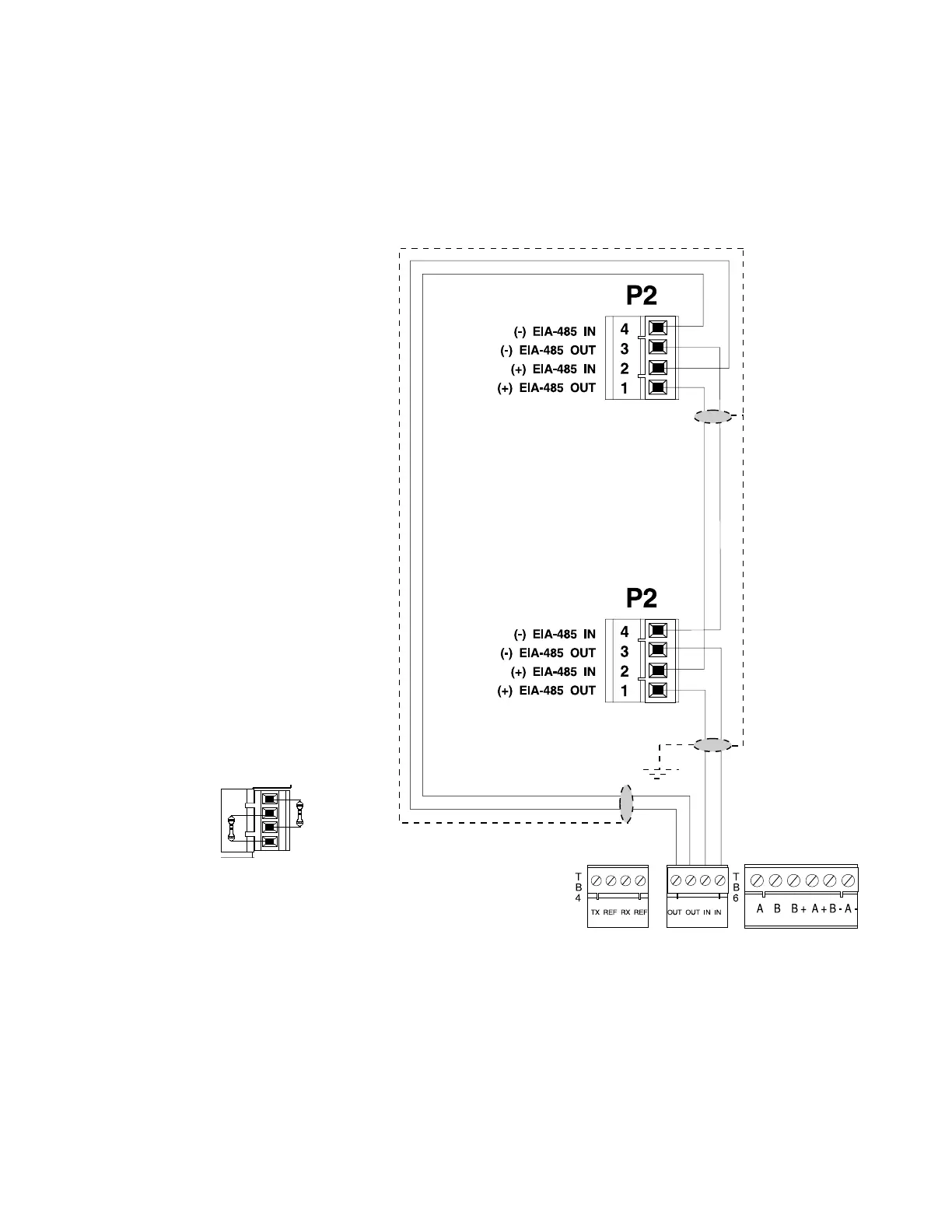
• Each LCD-80 must have R-120 re-
sistors installed across the in and out
terminals as shown below.
Figure C-1 Terminal Mode EIA-485 Connection
TB5-1 (+)
TB5-2 ()
First LCD-80
(must set DIP Switch SW3-1 AND SW3-2 "OFF" on
all LCD-80 's except the last one)
(SW3-1 and SW3-2 must be
set ON on the last LCD-80)
T
B
5
Note: The LCD-80s require connection of operating power! Connect 24 V power to the AFP-200 TB1 terminal
3 (+) and TB1 terminal 4 (–). Power connections are supervised and power-limited.
Last LCD-80 Last LCD-80
Last LCD-80 Last LCD-80
Last LCD-80
Terminal Mode EIA-485 Connections