Installation Addressable Module Mounting
16 FCPS-24S PN 51977:C1 08/06/03
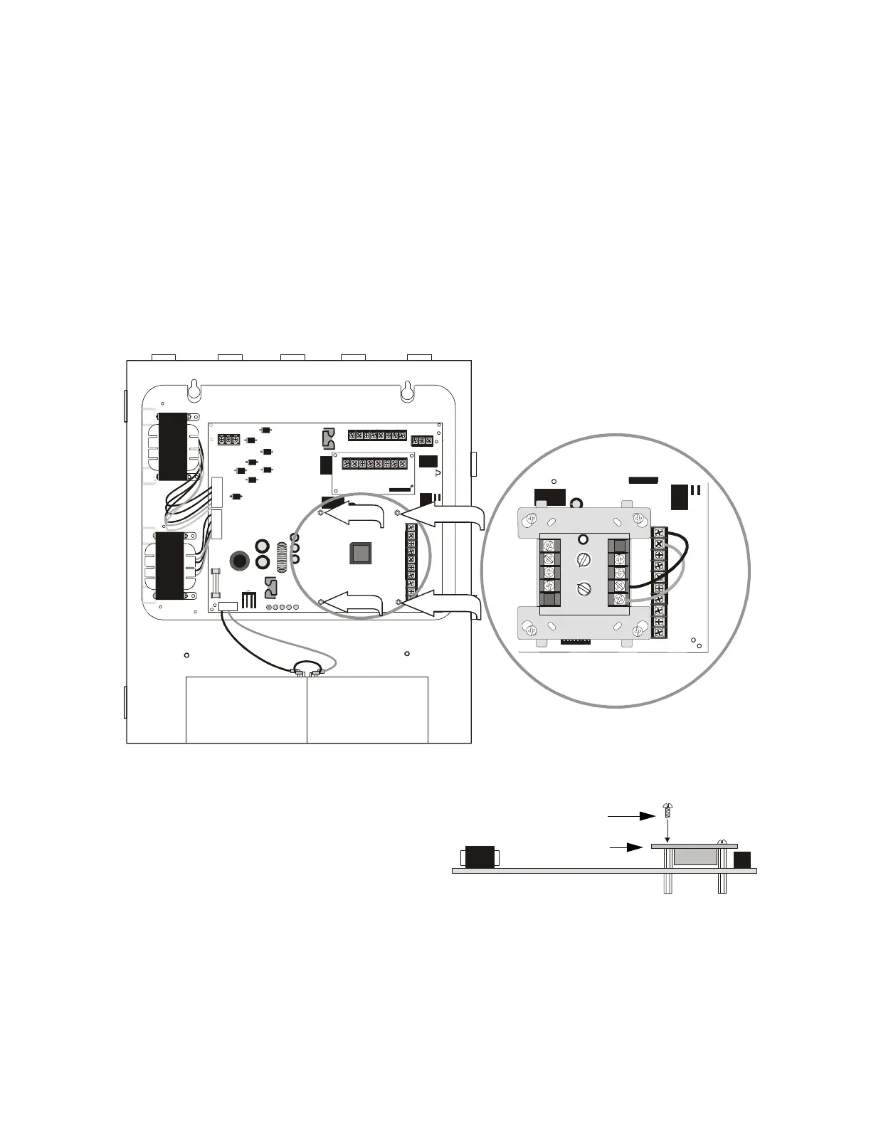
2.3 Addressable Module Mounting
The FCPS-24S has been designed to allow the mounting of an addressable control,
relay or monitor module on the main circuit board inside the power supply cabinet with
the module status LED visible through the closed door. This allows power to be fed
from the FCPS-24S Auxiliary Power output directly to the module, if needed, without
running the power wires outside the cabinet. As an example, Figure 2.5 illustrates
wiring from the Auxiliary power output terminals to a FMM-1 control module’s
terminals 3 (-) and 4 (+).
Note: The module mounting kit (P/N 90286) is pre-installed on the power supply main
circuit board.
1 2 3 4 5 6 7 8
ON
1 2 3 4 5 6 7 8
ON
TB1
J2
TRANSFORMER 2 TRAN SFORMER 1
J1
F1
JP4
30V
15A
SW1
SW1
TB4
TB4
JP3
JP3
J3
TB5
TB2
JP1
JP2
JP2
+ -
EARTH NEUT HOT
OUT4
- NAC4 +
OUT3
- NAC3 +
OUT2
- NAC2 +
OUT1
- NAC1 +
AUX -
AUX -
IN2-
IN2-
IN2+
IN2+
OUT1-
OUT1-
OUT1+
OUT1+
IN1-
IN1-
IN1+
IN1+
SYN C IN -
SYNC IN -
SYNC IN +
SYNC IN +
AUX +
AUX +
NO NC
AUX TBL
COM
BATTERY
AC BATT
GND
FLT
NAC
TRBL
AC/
CHGR
CAUTION
HIGH VOLTAGE
CAUTION
HIGH VOLTAGE
NAC 4 CLASS A
A- A+
NAC 3 CLA SS A
A- A+
NAC 2 CLASS A
A- A+
NAC 1 CLA SS A
A- A+
8
9
8
8
9
9
10
11
12
13
14
150
0
1
1
2
2
3
3
4
4
5
5
6
6
7
7
0
1
2
3
4
7
6
5
TENS
ONES
DDRESS
LOOP
Module Installation
1. Place addressable module over (4) standoffs and
secure with (4) supplied screws.
2. Wire module as show in illustration above.
Figure 2.5 Mounting Module In FCPS-24S Cabinet
standoff
standoff
standoff
standoff
24fsmodlNOTI.cdr
addressable module
mounting screw
24fsmodinstlNOTI.cdr
www.PDF-Zoo.com