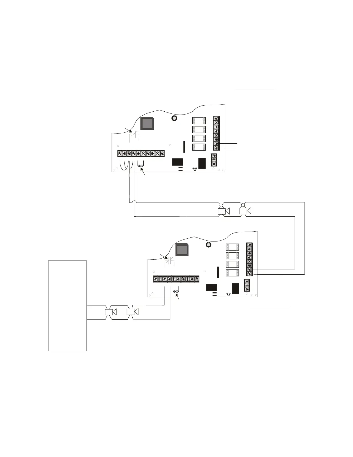
Applications Cascaded FCPS-24S Supplies from Nonsynchronized Source
36 FCPS-24S PN 51977:C1 08/06/03
5.8 Cascaded FCPS-24S Supplies from Nonsynchronized Source
In this application, multiple slave FCPS-24S power supplies are cascaded from a master power
supply which is connected to an FACP NAC with nonsynchronized output. Each power supply
should be set for synchronization which matches the master power supply. A maximum of ten
cascaded supplies can maintain synchronization using System Sensor and Wheelock devices while
a maximum of four can maintain synchronization using Gentex devices.
Note: The following notes apply to this illustration
1. Refer to NFPA 72, Chapter 4-4, Visible Characteristics, Public Mode.
2. Use only devices from the same manufacturer in each system.
FACP
NAC
with no
synchronization
NAC 1
-
+
TB4
JP3
J3
TB5
TB2
JP1
JP2
OUT4
-N
C4+
OUT3
-N
C3+
OUT2
-N
C2+
OUT1
-NAC1+
AUX -
IN2-
IN2+
OUT1-
OUT1+
IN1-
IN1+
SYNC IN -
SYNC IN +
AUX +
NO NC
AU
TBL
COM
1 2 3 4 5 6 7 8 9 10
8
7
6
5
4
3
2
1
8
7
6
5
4
3
2
1
3
2
1
TB4
JP3
J3
TB5
TB2
JP1
JP2
OUT4
-NAC4+
OUT3
-NAC3+
OUT2
-NAC2+
OUT1
-NAC1+
AUX -
IN2-
IN2+
OUT1-
OUT1+
IN1-
IN1+
SYNC IN -
SYNC IN +
AUX +
NO NC
AUX TBL
COM
1 2 3 4 5 6 7 8 9 10
3
2
1
Internal
Trouble
Contact
Internal
Trouble
Contact
ELR
for FACP
NAC
4.7K
ELR for
FCPS-24S
Output
Ω
Standby Polarity Shown
Horns
(no synchronization)
FCPS-24S
FCPS-24FS
SW1 Switch Settings
1 & 2 = sync (any setting but OFF/OFF)
3 = ON (slave)
4 = OFF (no AC Fail reporting delay)
5 = OFF
6 = OFF
7 = OFF (charger enabled)
8 = OFF (circuit 4 NAC)
(general alarm)
SW1 Switch Settings
1 & 2 = sync (any setting
but OFF/OFF)
3 = OFF (master)
4 = OFF (no AC Fail
reporting delay)
5 = OFF
6 = OFF
7 = OFF (charger enabled)
8 = OFF (circuit 4 NAC)
Figure 5.8 Supervised Cascaded Connections
general alarm
24fsapp11.cdr
to next FCPS-24S input
(if needed)
Horn/Strobes
(synchronized)
Note: One Relay Module can be mounted
directly to each FCPS-24S circuit board
inside the power supply cabinet.
www.PDF-Zoo.com