Door Release Service For All Four Outputs Applications
FCPS-24S PN 51977:C1 08/06/03 33
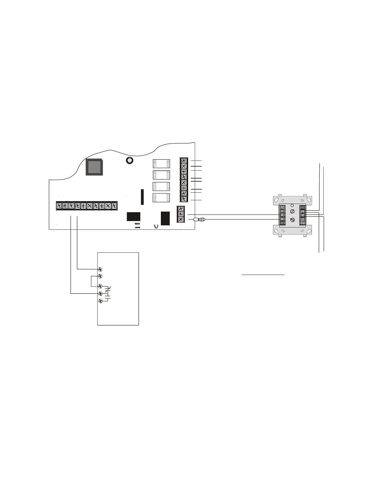
5.5 Door Release Service For All Four Outputs
This application illustrates the use of the FCPS-24S to power 24 VDC door holders.
The power supply must be set for General Alarm. A signal must be supplied from the
FACP to activate the FCPS-24S outputs. This signal should consist of a +24 VDC
nonresettable source connected through the FACP Normally Closed alarm contacts.
During normal (nonalarm) condition, the +24 VDC should be applied to the FCPS-24S
Control Input 1. This will result in the outputs of the power supply being activated
which will in turn energize the door holders. When the FACP enters an alarm
condition, the alarm contacts will open, removing the +24 VDC signal from the
FCPS-24S, causing the door holders to release. It is important to note that, for this
application, doors will close immediately on activation of an alarm condition. AC loss,
however, will switch to batteries in sufficient time to prevent doors from closing.
Notes: The following notes apply to Figure 5.5.
1. During a normal (nonalarm) condition, nonresettable +24 VDC should be applied
to TB4, Terminal 3 (-24 VDC is applied directly to Terminal 4 from the FACP)
2. The Normally Closed alarm relay may consist of an actual relay in the FACP or a
control module which may be mounted remotely or at the FACP.
3. A monitor module may be used to monitor the FCPS-24S Trouble contacts at
TB5. Any power supply trouble will cause the contacts to change states.
4. A maximum of 4.0 amps from the FCPS-24S6 and 6.0 amps from the
FCPS-24S8 may be drawn continuously for holding doors
5. For a list of compatible devices, refer to the Device Compatibility Document
6. An alarm condition will cause the doors to close immediately.
TB4
JP3
J3
TB5
TB2
JP1
JP2
OUT4
-NAC4+
OUT3
-NAC3+
OUT 2
-NAC2+
OUT 1
-NAC1+
AUX -
IN2-
IN2+
OUT1-
OUT1+
IN1-
IN1+
SYNC IN -
SYNC IN +
AUX +
NO NC
AUX TBL
COM
1 2 3 4 5 6 7 8 9 10
-24 VDC
Nonresettable
Alarm
Relay
FACP
+24 VDC
8
7
6
5
4
3
2
1
3
2
1
8
9
8
8
9
9
10
11
12
13
14
150
0
1
1
2
2
3
3
4
4
5
5
6
6
7
7
0
1
2
3
4
7
6
5
TE NS
ONE S
ADDRESS
LOO P
Figure 5.5 Using the FCPS-24S with 24 VDC Door Holders
SW1 Switch Settings
1 = OFF
2 = OFF
3 = OFF (master)
4 = OFF (no AC Fail reporting delay)
5 = OFF
6 = OFF
7 = OFF (charger enabled)
8 = OFF (circuit 4 NAC)
No Sync
General Alarm
Monitor Module
FCPS-24S
Door Holder Circuit 4
Door Holder Circuit 3
Door Holder Circuit 2
Door Holder Circuit 1
End-of-Line Resistor
supplied with
Monitor Module
SLC
SLC
24fsapp3.cdr
www.PDF-Zoo.com