Split Temporal Mode of Operation Applications
FCPS-24S PN 51977:C1 08/06/03 29
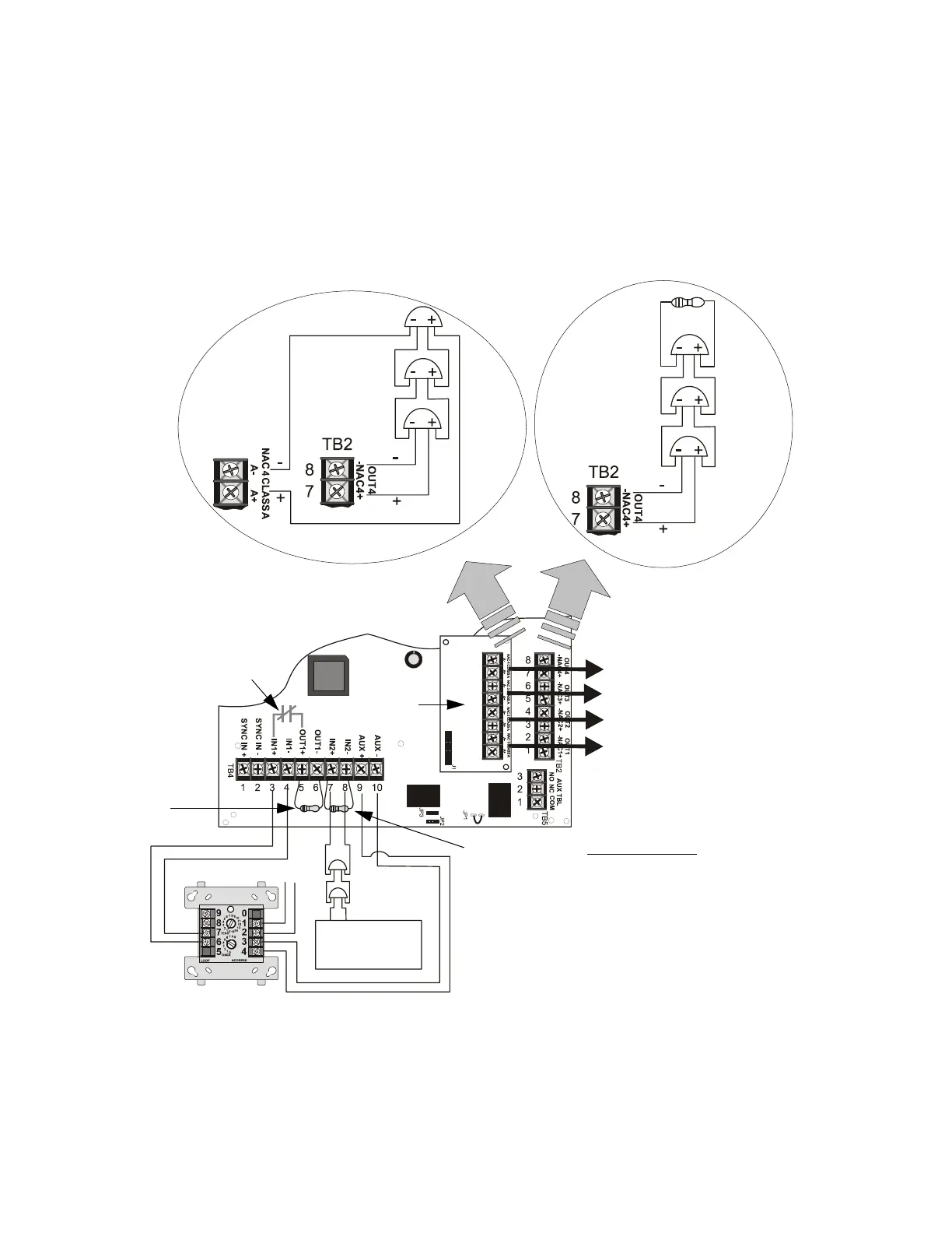
5.3 Split Temporal Mode of Operation
In this application, the power supply has been set as a master with two synchronized
and two nonsynchronized outputs as determined by the Split Temporal mode feature.
Control Input #1 (TB4, Terminals 3 & 4) is connected to an addressable control module
which will cause the synchronized power supply output circuits 1 & 2 to turn on.
Control Input #2 (TB4, Terminals 7 & 8) is connected to an FACP Notification
Appliance Circuit which is used to activate the power supply’s temporal output circuits
3 & 4.
Figure 5.3 Split Temporal Mode Application
Style Z (Class A)
Style Y (Class B)
Temporal Bell Circuit 4
Temporal Bell Circuit 3
Horn/Strobe Circuit 2
Horn/Strobe Circuit 1
Use listed ELR
(4.7KΩ) to
terminate Style Y
(Class B) NAC
ELR not required for
Style Z (Class A) NAC
Note: All NACs are supervised and power-limited
ZNAC-4
Option Module
SW1 Switch Settings
1 & 2 = sync (any setting but OFF/OFF)
3 = OFF (master)
4 = OFF (no AC Fail reporting delay)
5 = ON
6 = OFF
7 = OFF (charger enabled)
8 = OFF (circuit 4 NAC)
Internal Trouble Contact
Split Temporal
FACP
NAC
(steady,
no sync)
Control Module
End-of-Line Resistor
supplied with Control
Module
FACP NAC
End-of-Line
Resistor
FCPS-24S
Bells
Bells
SLC
24fsapp5.cdr
www.PDF-Zoo.com