Applications Multiple Synchronized FCPS-24S Power Supplies
34 FCPS-24S PN 51977:C1 08/06/03
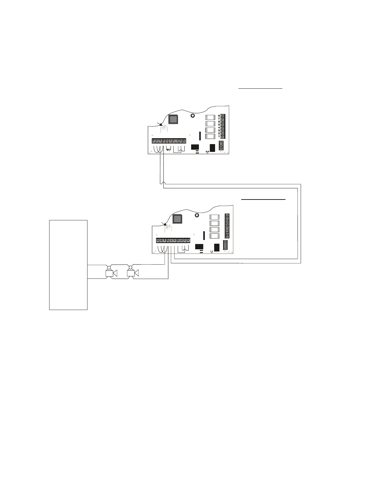
5.6 Multiple Synchronized FCPS-24S Power Supplies
In this application, multiple FCPS-24S power supplies, configured as Slave units, are
connected to a master FACP NAC programmed for synchronized output. Each power
supply should be set for synchronization which matches the FACP programming.
Note: FACP supplied selective silence function outputs will follow panel input.
Note: The following notes apply to Figure 5.6
1. Refer to NFPA 72, Chapter 4-4, Visible Characteristics, Public Mode.
2. The NAC output devices from one power supply must be partitioned with walls
and/or floors from the next power supplies and their NAC output devices.
3. Use only devices from the same manufacturer in each system.
4. Relay Modules programmed as silenceable points will selectively silence the
notification appliances when its Normally Open contact (7 & 9) closes
FACP
NAC
programmed
for Sync
NAC 1
-
+
TB4
JP3
J3
TB5
TB2
JP1
JP2
OUT4
-N
C4+
OUT3
-N
C3+
OUT2
-N
C2+
OUT1
-N
C1+
U
-
IN2-
IN2+
OUT1-
OUT1+
IN1-
IN1+
SYNC IN -
SYNC IN +
U
+
NO NC
U
TBL
COM
1 2 3 4 5 6 7 8 9 10
8
7
6
5
4
3
2
1
3
2
1
TB4
JP3
J3
TB5
TB2
JP1
JP2
OUT4
-NAC 4+
OUT3
-NAC3+
OUT2
-NAC 2+
OUT1
-NAC1+
AUX -
IN2-
IN2+
OU T1-
OUT1+
IN1-
IN1+
SYNC IN -
SYNC IN +
AUX +
NO NC
AUX TBL
COM
1 2 3 4 5 6 7 8 9 10
3
2
1
Internal
Trouble
Contact
Internal
Trouble
Contact
ELR
Standby Polarity Shown
Horn/Strobes
FCPS-24S
FCPS-24S
SW1 Switch Settings
1 & 2 = sync (any setting but OFF/OFF)
3 = ON (slave)
4 = OFF (no AC Fail reporting delay)
5 = OFF
6 = OFF
7 = OFF (charger enabled)
8 = OFF (circuit 4 NAC)
general alarm
SW1 Switch Settings
1 & 2 = sync (any setting
but OFF/OFF)
3 = ON (slave)
4 = OFF (no AC Fail
reporting delay)
5 = OFF
6 = OFF
7 = OFF (charger enabled)
8 = OFF (circuit 4 NAC)
Figure 5.6 Supervised Master/Slave Connections
general alarm
Note: One Relay Module can be mounted
directly to each FCPS-24S circuit board
inside the power supply cabinet.
24fsapp1.cdr
www.PDF-Zoo.com