Jumpers System Overview
FCPS-24S PN 51977:C1 08/06/03 9
1.4 Jumpers
CAUTION! Remove all power (AC & DC) before cutting or moving any jumpers.
1.4.1 Jumper JP1 - Ground Fault Detection
Jumper JP1 is located in the top right section of the power supply circuit board. Cutting
JP1 will disable ground fault detection by the power supply. This should only be done
if ground faults are being monitored by a panel connected to the FCPS power supply.
1.4.2 Jumpers JP2 and JP3:
Coded/Noncoded Input Selection
Jumpers JP2 and JP3 are located in the top right section of the power supply circuit
board. JP2 is used for Control Input Circuit #1 and JP3 is used for Control Input Circuit
#2. The position of these jumpers will depend on the type of signal being fed to the
input circuits:
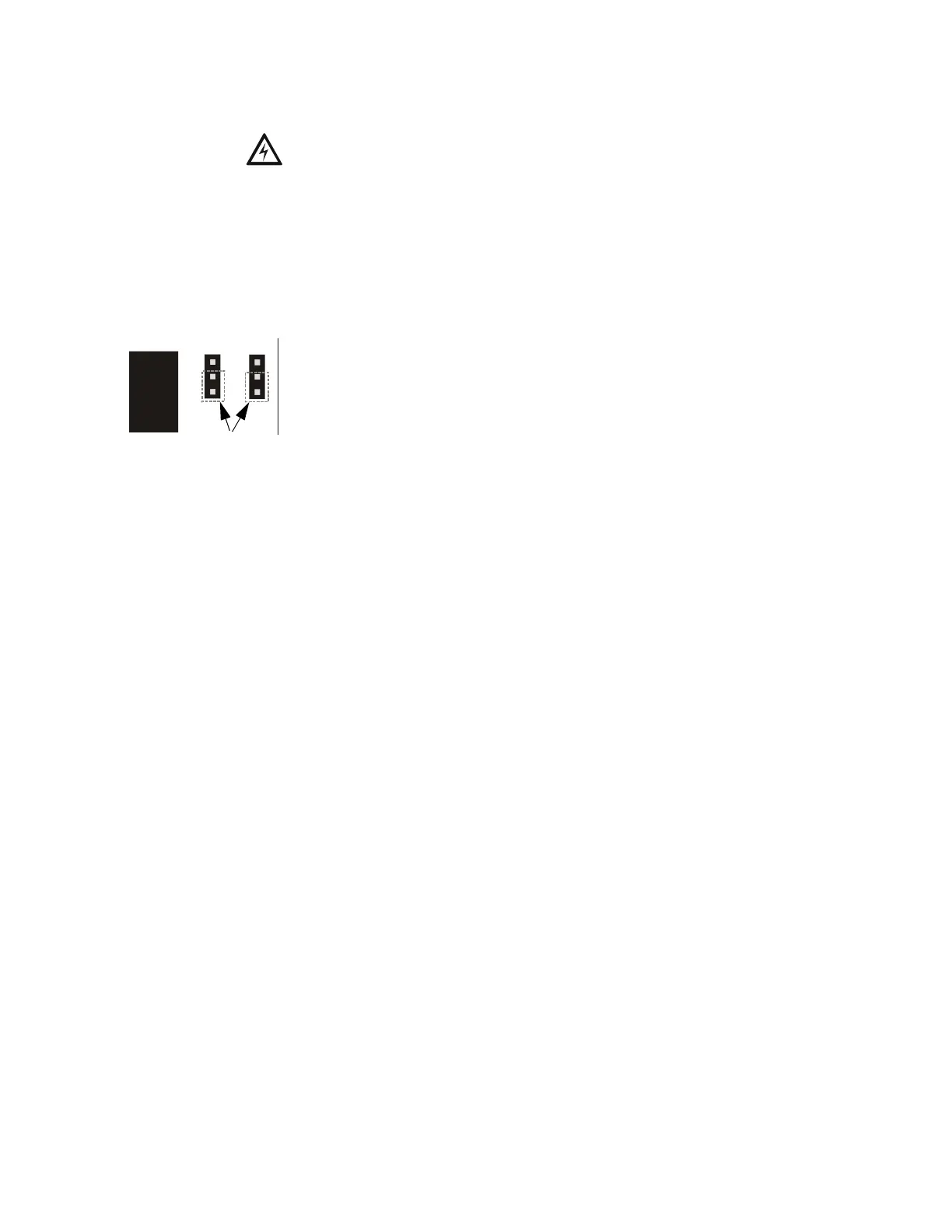
• If the source voltage to the input circuit is a noncoded (steady voltage) input
signal, the jumper for the corresponding input circuit should be in the default
position which jumpers the bottom two pins (as illustrated in drawing at left).
• If the source voltage to the input circuit is coded (variable voltage), the jumper
for the corresponding input circuit should be moved to jumper the top two pins.
1.5 LED Indicators
• AC Power on (green) LED - indicates AC power is present
• Ground Fault (yellow) LED - indicates a ground fault condition
• Battery Trouble (yellow) LED - indicates low or no battery
• NAC Trouble (yellow) LED - indicates a Notification Appliance Circuit trouble
(blinks once for Circuit 1 trouble, twice for Circuit 2 trouble, three times for
Circuit 3 trouble and four times for Circuit 4 trouble. Note that multiple circuits
in trouble will cause the LED to blink the number of the circuit with the highest
number)
• ChargerTrouble/AC Loss (yellow) LED - indicates a charger fault or loss of AC
power
Jumper positions shown
for noncoded (steady)
source voltage
JP3
JP2
jumpers
24s8jp3b.cdr
www.PDF-Zoo.com