Applications Controlling Four NACs With One Input and Selective Silence
26 FCPS-24S PN 51977:C1 08/06/03
Notes: The following notes apply to Figure 5.1 on page 25.
1. When the FCPS-24S power supply is in an inactive state (control module not
active), a trouble on the power supply will result in an open circuit condition on
the control module output circuit (monitored by End-of-Line Resistor across
TB4, Terminals 5 & 6). As an alternative, the trouble contacts at TB5 of the
power supply can also be used for independent trouble monitoring.
2. The addressable relay module must be programmed as a silenceable point at the
FACP to allow selective silence of horn/strobe devices. The Normally Open
contact of the relay module is connected between TB4 Terminal 7 (IN2 +) and
Terminal 9 (Aux. Power +).
3. Do not loop wires under screw terminals. Break wires to maintain proper
supervision.
4. An End-of-Line Resistor must be installed between TB4, Terminals 5 & 6 for
control module wiring supervision (the ELR value is dependent on the module
employed).
5. Supervise the power wiring between the FPCS-24S auxiliary 24 VDC output on
TB4, Terminals 9 & 10 with an EOL relay (P/N: A77-716B)
6. For a list of compatible devices, refer to the Device Compatibility Document.
7. IMPORTANT! When the power supply is programmed for both Selective
Silence and Slave Mode, TB4 Terminal 7 (IN+) must be jumpered to Terminal 9
(AUX+) and Terminal 8 (IN-) must be jumpered to Terminal 10 (AUX-). The
FACP will control the Selective Silence feature with this configuration.
If the terminals are not jumpered as indicated, the horn portion of the horn/
strobes will be silenced
at all times.
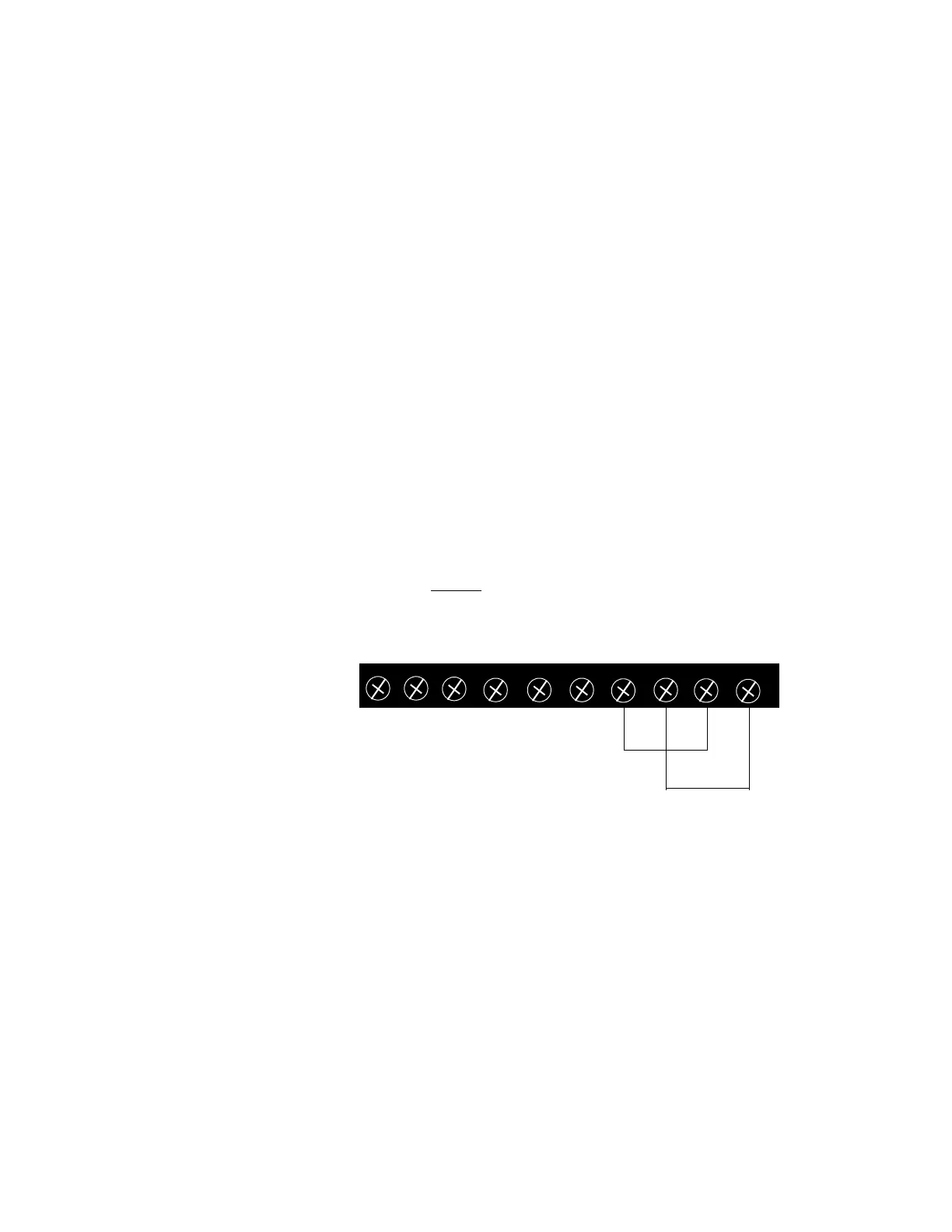
TB4
1 2 3 4 5 6 7 8 9 10
SYNC SYNC IN+ IN- OUT+ OUT- IN2+ IN2- AUX+ AUX-
www.PDF-Zoo.com