Nox A1 Manual
~ 21 ~
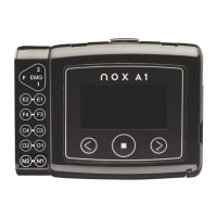
Connect the Nox EEG Head Cable to the E2-E1, F4-F3, C4-C3, O2-O1, M2-M1 unipolar and ground
inputs of the Nox A1 recorder.
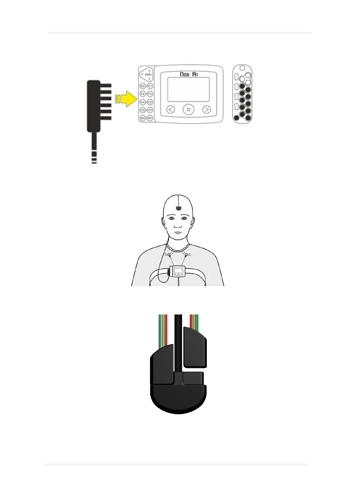
Place a snap-on electrode on the middle of the patient’s forehead. Route the Nox EEG Head Cable
behind the patient’s head and snap the cable to the electrode.
Connect two Nox 5 Lead EEG Electrode Cables to the head cable, one on each side.
Attach the gold cup electrodes to the patient’s head. The green wire is for E1/E2, the blue wire is for
F3/F4, the yellow wire is for C3/C4, the grey wire is for O1/O2 and the red wire is for M1/M2.