32
ROTARY JOINT MAINTENANCE
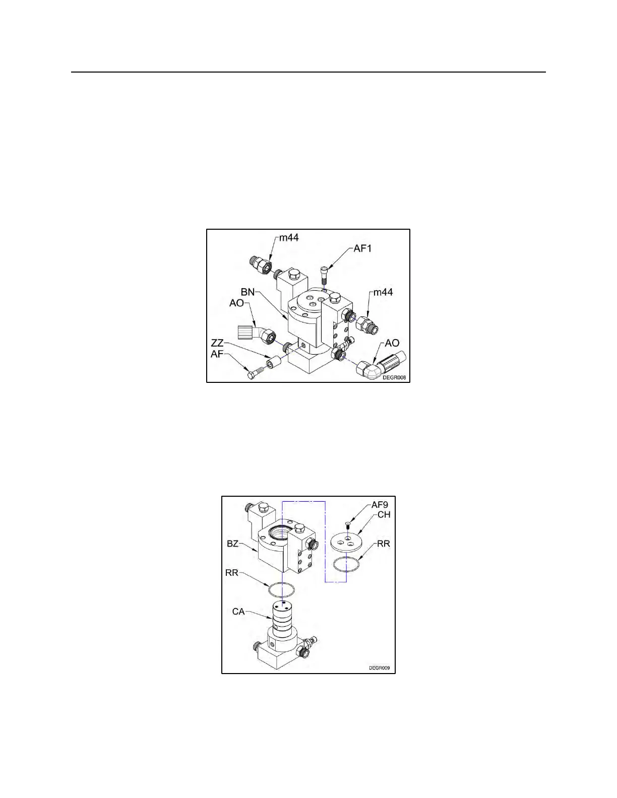
REPLACEMENT OF THE SEALS IN THE ROTARY JOINT
Step 1
Remove the top bracket from the swivel flat top assembly. Remove the joint fitting
adapter fittings (m44) from the spindle case manifold blocks. Remove the hoses (AO)
from the spindle base manifold. Remove the bolt (AF) and spacer (ZZ) from the spindle
base manifold. Remove the four mounting bolts (AF1) from the spindle case. Pull the
rotary joint assembly (BN) from the swivel flat top assembly.
Figure 1
Step 2
Remove the three flat head socket screws (AF9). Remove the top plate (CH) and o-ring
(RR) from the spindle case (BZ). Remove the spindle case and o-ring from the spindle
(CA).
Figure 2