MAINTENANCE 12. TROUBLE SHOOTING
12. TROUBLE SHOOTING
Error causes and countermeasures are described below.
12-1. Error Displays and Countermeasures
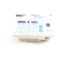
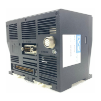
Displays the error on VARICAM when VARICAM or ABSOCODER has an error.
Refer to the following list and implement appropriate countermeasures.
● Lists of the error displays, probable causes, and error cancel procedures
Error display Name
Output
Probable cause Error cancel procedure
blinks
RDY.LED is
Sensor power
supply error
All output is
OFF.
The power supply inside of
VARICAM for sensor breaks down.
Replace VARICAM.
For more details, refer to the chapter 12-2.
blinks
RDY.LED is
OFF
Sensor error
All output is
OFF.
Sensor connector is disconnected
and loose.
After removing the error causes, cancels the
error following methods:
- Presses [CLR] or [ON / OFF] key.
- Inputs the error cancel signal from external.
Sensor cable is severed.
Replace the sensor cable.
For more details, refer to the chapter 12-2.
Failure of ABSOCODER
Replace ABSOCODER.
For more details, refer to the chapter 12-2.
Failure of VARICAM
Replace VARICAM.
For more details, refer to the chapter 12-2.
blinks
RDY.LED is
OFF
Memory error
All output is
OFF.
Memory data has been changed
due to external noise, etc.
Do the initialization operation.
For the operation method, refer to the
chapter 12-3.
NOTE
Data needs to reset up because the
parameter and switch output setting
blinks
“No setting”
error
-
Only ON angle was set up when
setting a switch output.
(OFF angle is not set.)
Cancel the error by pressing [CLR] or
[ON / OFF] key.
OFF angle also needs to set after resetting
blinks
Setting error
-
The ON angle is set overlapped
values when setting a multi-dog.
Cancel the error by pressing [CLR] or
[ON / OFF] key.
Sets the correct value at ON angle.
SYS-
is ON
System error
All output is
OFF.
The power supply voltage is low.
Replace the power supply.
Failure of VARICAM
Replace VARICAM.
For more details, refer to the chapter 12-2.
is ON
RDY.LED is
OFF
Origin point
unset error
The output
is undefined
both switch
and BCD
signals.
The origin point is not set. Set the parameter No.98 or 99. For more
details, refer to the chapter 7-5-4 or 7-5-5.
 Loading...