16
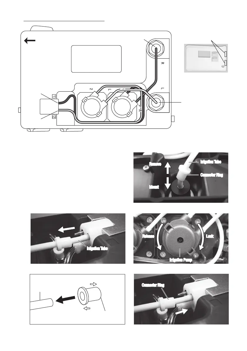
Fig.35
* Bottle side
Fig.36
* Front Panel side
Fig.39
* Front Panel side
3) Remove the Irrigation Tube from the Control Unit. (Bottle side and Front Panel side.) (Fig. 35, 36)
4) Remove the Connector Ring from the Irrigation Tube. Do not dispose it. You can use the Rings to the replacement
Irrigation Pump.
5) Turn the Irrigation Pump counterclockwise until it clicks
and pull it out. (Fig. 37)
6) Mount the Connector Ring to the new Irrigation Pump.
Observing Ring direction. (Fig. 38)
7) Align the replacement Irrigation Pump with the Drive Shaft.
Turn clockwise until it clicks. (Fig. 37)
8) Mount the Irrigation Tube opposite procedure of removing
(Fig.35). Connector Ring should firmly into the Control Unit
until it stops. (Fig.39)
Picture below is shows inside of the Control Unit.
Fig.34
Bottom Cover (Back Side)
Bottom Cover Hook
R Bottle Bottle Joint
Front Panel Side
L Bottle Bottle Joint
R Pump Tube Joint
L Pump Tube Joint
R PumpL Pump
Irrigation Tube
Fig.37
Irrigation Pump
Irrigation Tube
Connector Ring
Remove
Mount
Remove
Mount
Irrigation Tube
Connector Ring
Irrigation Tube
Release LockRelease Lock
Irrigation Pump
Connector RingConnector Ring
Fig.38
L/R Pump side
Irrigation Tube
Control Unit side
Connector Ring
 Loading...