EasyManua.ls Logo

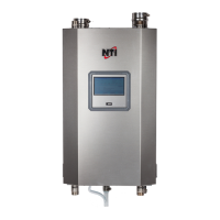
NTI Trinity Ti 200 - User Manual

Default Icon
38 pages
Print Icon
To Next Page IconTo Next Page
Loading...
1.0 SPECIFICATIONS..................................................................................................2
1.1 HIGH ALTITUDE OPERATION..................................................................................2
2.0 INSTALLATION REQUIREMENTS ...................................................................2
3.0 VENTING .................................................................................................................4
3.1 VENT PIPE MATERIAL ............................................................................................4
3.3 VENTING RULES AND GUIDELINES .........................................................................7
3.4 VENTING CLEARANCES ..........................................................................................7
4.0 CONDENSATE DRAIN..........................................................................................9
5.0 INSTALLING GAS PIPING...................................................................................9
5.0 INSTALLING GAS PIPING.................................................................................10
5.1 INSTALLATION......................................................................................................10
5.2 TESTING AND SETTINGS ........................................................................................10
6.0 HEATING SYSTEM PIPING...............................................................................12
6.1 PRIMARY LOOP PLUMBING...................................................................................13
6.2 SECONDARY LOOP HEATING SYSTEM ..................................................................16
6.2.1 Multiple Zones using Zone Valves.............................................................16
6.2.2 Multiple Zones using Pumps......................................................................16
6.2.3 Multiple Zones with Different Temperatures............................................17
6.3 DOMESTIC COMBI SYSTEM...................................................................................18
7.0 WIRING..................................................................................................................20
7.1 SIMPLIFIED WIRING CONNECTIONS......................................................................21
7.2 ADVANCED WIRING SYSTEMS..............................................................................22
7.2.1 Multiple 4 wire Zone Valves.......................................................................22
7.2.2 Multiple Zones with Taco Valve controller................................................23
7.2.3 Multiple Zones Pump controller................................................................24
7.2.4 Multiple Temperature Zones with Injection Pumps..................................25
8.0 SENTRY 2100 CONTROLLER ...........................................................................26
9.0 LIGHTING BOILER.............................................................................................30
9.1 INITIAL START-UP.................................................................................................30
9.2 RE-LIGHTING UNIT...............................................................................................30
9.3 TURN OFF BOILER.................................................................................................30
10.0 TROUBLE SHOOTING......................................................................................31
11.0 SEQUENCE OF OPERATION ..........................................................................34
14.0 ANNUAL MAINTENANCE AND INSPECTION............................................36
14.1 COMBUSTION CHAMBER CLEANING...................................................................36
15.0 PARTS LIST.........................................................................................................37
CAUTION:
IT IS THE RESPONSIBILITY OF THE HOMEOWNER TO
KEEP THE VENT TERMINAL CLEAR OF SNOW AND ICE.
Trinity Ti Boiler Only
VERSION DATE: 1-5-2010
Installation and
Operation Instructions
Trinit
y
Ti
This Boiler must be installed by a licensed and trained Heating
Technician; otherwise the warranty of this unit is void. Failure
to properly install this unit could cause damage to property
and injury to occupants possibly resulting in death.

Other manuals for NTI Trinity Ti 200

Questions and Answers

  • G
    gsmithSep 7, 2025
    What does Three Flashes on Fenwal mean for NTI Trinity Ti 200?
    • J
      jonesandreaSep 7, 2025
      If the Fenwal displays three flashes on your NTI Boiler, it indicates that if the condensate drain gets blocked, the boiler will become flooded and terminate operation, as the flame rod becomes immersed. This will damage the flame probe. To correct this, clear the drain blockage and prevent it from happening again. Remove and dry the probe. Reinstall the probe and try for ignition. If it fails, leave the fan running for up to three hours to dry out the insulation and probe.
  • B
    Brandi CarrollSep 9, 2025
    What does Two Flashes on Fenwal mean for NTI Trinity Ti 200 Boiler?
    • N
      nathan36Sep 9, 2025
      If the Fenwal displays two flashes on your NTI Boiler, and the combustion sequence is normal with no flame before ignition, the Fenwal control is defective and must be replaced.
  • E
    eric84Sep 13, 2025
    Why does my NTI Trinity Ti 200 show ER6?
    • I
      Ian LeeSep 13, 2025
      The ER6 error on your NTI Boiler indicates that the Sentry control has detected a lack of 24V to the gas valve during operation or a Fenwal ignition lockout. This indicates a problem in the ignition sequence, which may stem from a faulty igniter, flame sensor, or gas valve, or from improper line pressure or combustion. Check the ignition sequence to identify the malfunctioning component. Note that the Sentry control will retry the ignition sequence one hour after the ER6 code first appears, or if the control is reset.
  • T
    timothy28Sep 14, 2025
    How to fix ER1 on display on NTI Trinity Ti 200 Boiler?
    • K
      Kelly SmithSep 14, 2025
      The ER1 error code on your NTI Boiler means the Sentry has detected a water temperature exceeding 250ºF at the Water Sensor. If the boiler is extremely hot, check for adequate water pressure and circulation, then contact NTI for assistance. If the boiler is not hot, inspect the Water Sensor electrical connections for grounding or shorting, and check the wiring from the Sensor to the Sentry Control. If the resistance of the Water Sensor is not within the correct range, replace it. (Refer to the resistance charts for 1 Mohm Trinity Thermister).
  • T
    Tina SmithSep 18, 2025
    Why does my NTI Trinity Ti 200 Boiler show ER3 on display?
    • J
      Joshua McdanielSep 18, 2025
      The ER3 error code on your NTI Boiler indicates that the Sentry has detected an open circuit in the Water Sensor circuit. Check the wiring to the Water Sensor for open circuits or shorting to ground. Note that ER3 will be displayed if the temperature sensed is less than 0°F. If the wiring is intact, replace the Water Sensor if its resistance is not within the correct range. Refer to the resistance charts for the 1 Mohm Trinity Thermister.

Summary

Specifications

Installation Requirements

Venting

Vent Pipe Material

Specifies approved materials for exhaust and air intake piping like PVC and CPVC.

Venting Rules and Guidelines

Provides rules for vent termination location, clearances, and piping slopes.

Venting Clearances

Defines code restrictions for flue gas vent terminal placement relative to windows, doors, and grade.

Condensate Drain

Installing Gas Piping

Installation

Covers gas piping installation requirements, referencing codes and flexible pipe usage.

Testing and Settings

Details line and manifold pressure requirements and gas valve adjustment procedures.

Heating System Piping

Wiring

Advanced Wiring Systems

Details wiring for multiple zones using zone valves, Taco controllers, and injection pumps.

Multiple Temperature Zones with Injection Pumps

Wiring for multiple zones with injection pumps and temperature controllers.

Sentry 2100 Controller

Setting the Sentry 2100

Guides on programming the Sentry 2100 controller via its push buttons and menu options.

Lighting Boiler

Initial Start-up

Outlines steps for initial boiler start-up, including checks for gas, water, and combustion.

Re-lighting Unit

Provides instructions for safely re-lighting the boiler burner, emphasizing safety precautions.

Trouble Shooting

Annual Maintenance and Inspection

NTI Trinity Ti 200 Specifications

General IconGeneral
Efficiency95% AFUE
Fuel TypeNatural Gas or Propane
Heating Capacity200, 000 BTU/h
Modulation Ratio5:1
Heat Exchanger MaterialStainless Steel
Water Connections1" NPT
VentingPVC, CPVC, or Polypropylene

Related product manuals