43
Part 1 - General Safety Information Part 5 - Venting
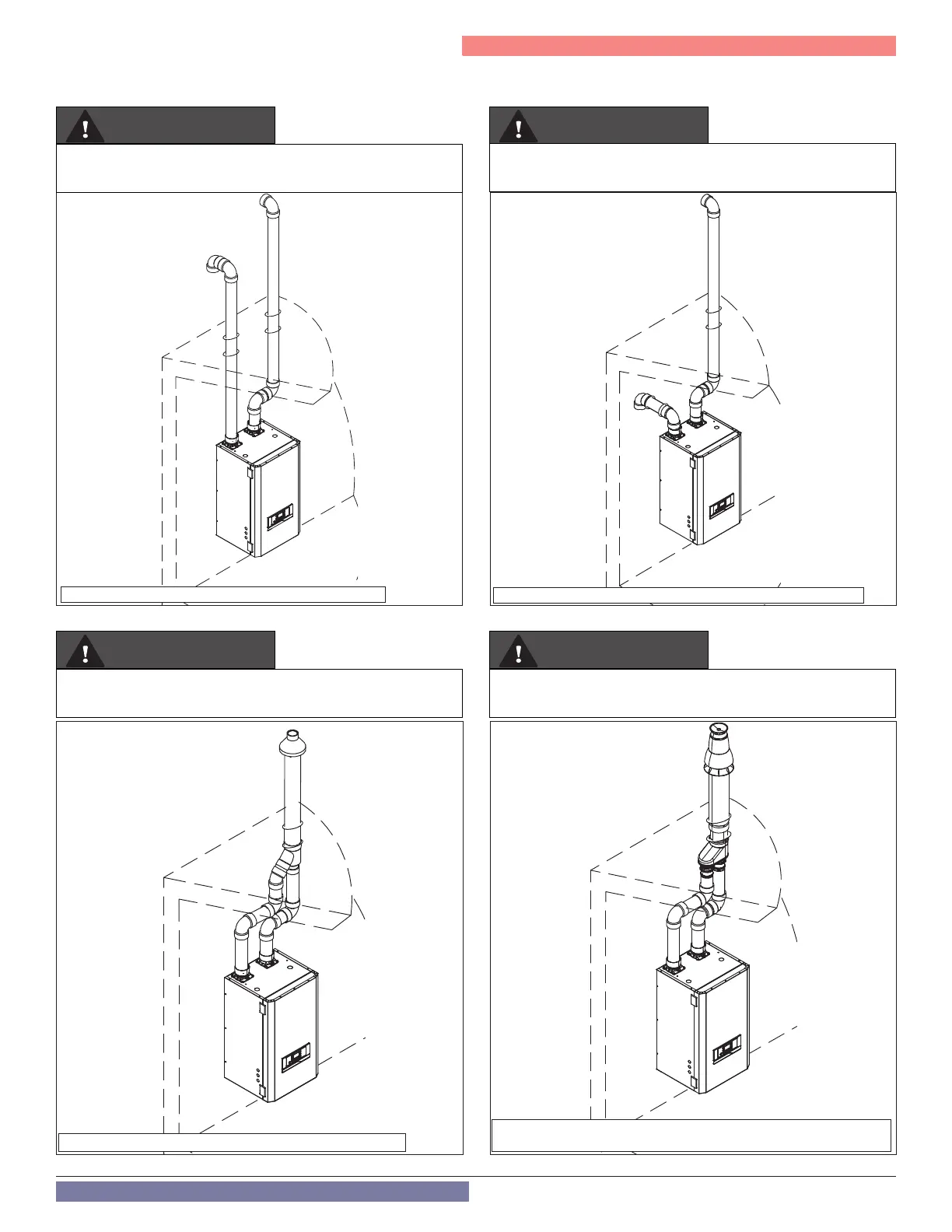
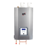
NOTE: These drawings are meant to demonstrate system venting only. The installer is responsible for all equipment and detailing required by local codes.
Roof Venting Options - Direct Vent Installation
Two Pipe Termination
Unbalanced Termination (Roof Exhaust / Sidewall Intake)
Concentric Termination
Intake
Exhaust
Exhaust
Intake
Intake
Exhaust
Intake
Exhaust
Exhaust must terminate a minimum of 18” above the air intake
termination. See Figure 37 for more details.
3” Polypro / Innoue Concentric Termination illustrated. See Figure 40
for more details.
3” IPEX Concentric Termination illustrated. See Figure 39 for more
details.
WARNING
WARNING
WARNING
WARNING
Figure 33 - Two Pipe Roof Venting
Figure 35 - Roof Concentric Termination (with Optional IPEX kit)
Figure 34 - Unbalanced Venting - Roof Exhaust and Sidewall Intake
Figure 36 - Roof Concentric Termination (with Optional Duravent /
InnoFlue Kit)
Exhaust must terminate a minimum of 12” above snow level. See Figure
38 for more details.