4001 non-addressable control and indicating equipment
Installation and Service Manual
10
32-0002-r12_2018-09
© 2015 ~ 2018 Ambest Electronics (Ningbo) Co Ltd. All rights reserved.
All specifications and other information shown were current at the date of publication and subject to change without notice.
6. INSTALLATION
6.1. Safety
ELECTRICAL HAZARD: Disconnect power from equipment prior to making any internal adjustments. This
equipment must have an Earth connection.
FRAGILE: Inspect the equipment prior to installation. Do not install the equipment if damage is apparent. If
damaged, return to the supplier.
ELECTROSTATIC HAZARD: This is sensitive electronic equipment. Apply safe ant-static practices when
handling this equipment.
CIRCUIT LIMITATIONS: The maximum number of detectors connected to a single detection zone is limited
by the control and indicating equipment, and may be limited by local regulations.
GENERAL CAUTIONS: This equipment must be installed by a suitably qualified and technically competent
person. A basic knowledge and training in the installation of fire detection and alarm systems is assumed. The
system should be designed by a suitably qualified person with reference to local regulations and guidance
from the fire officer where applicable. Service should only be performed by qualified personnel.
6.2. Tools and Equipment
Before commencing installation, ensure all equipment and tools to mount and connect the equipment are
available, such as drills, mounting screws, cables and ladders.
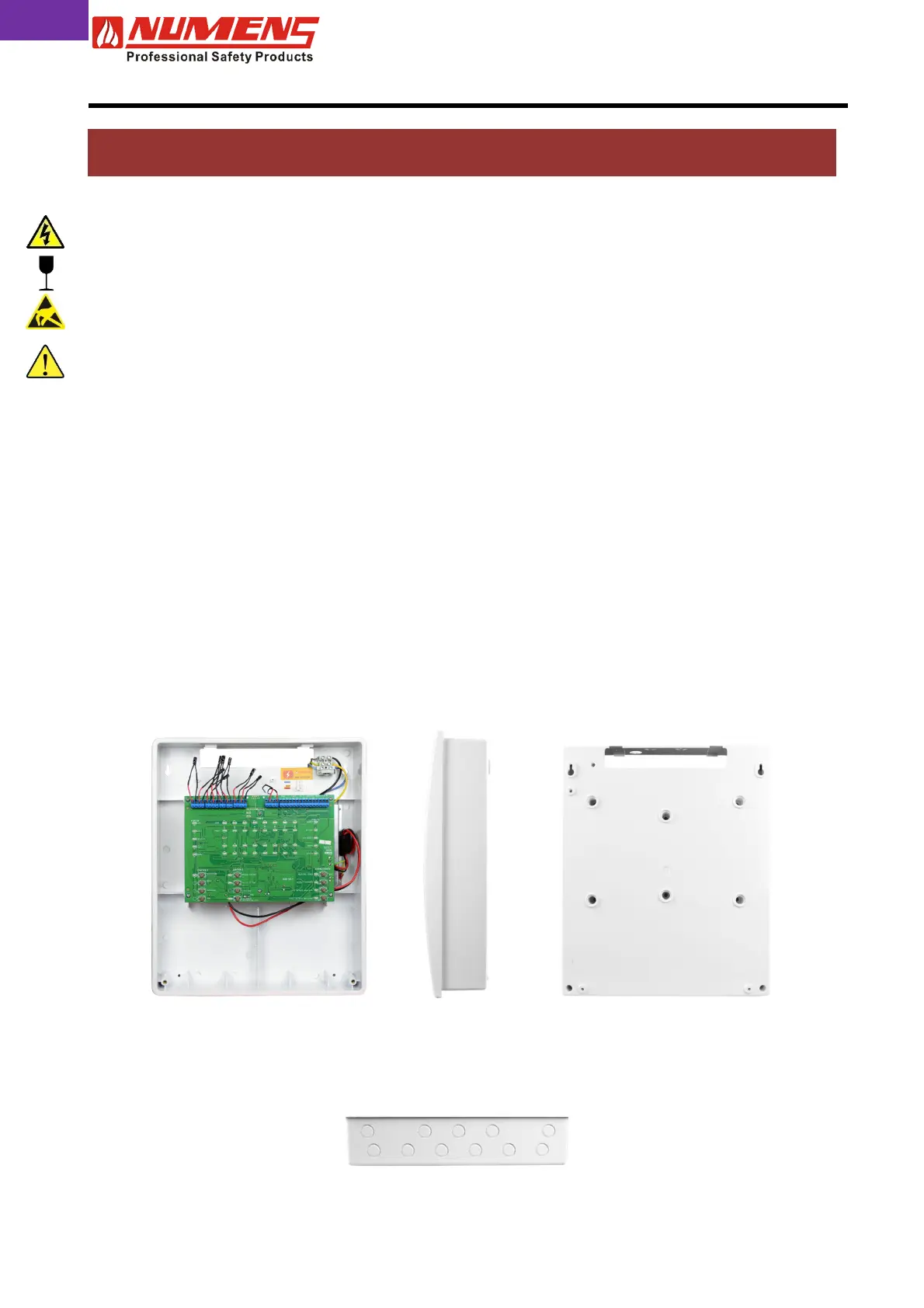
6.3. Control and Indicating Equipment Mounting
The 4001 is designed for recessed mounting, but may also be surface-mounted. Cable entry points are
provided at the top and back of the housing. Do not drill additional holes as cables could then interfere with
the PCB or battery location. Maintain separation between the incoming mains voltage cable and the extra-low
voltage input and output device cabling.
Fix the panel to the wall using the four mounting holes provided and No. 8-10 countersunk screws. Any dust
created during the fixing process must be kept out of the control and indicating equipment and care must be
taken not to damage any wiring or internal components.
Front view
Side view
Rear view
Top view
 Loading...