4001 non-addressable control and indicating equipment
Installation and Service Manual
14
32-0002-r12_2018-09
© 2015 ~ 2018 Ambest Electronics (Ningbo) Co Ltd. All rights reserved.
All specifications and other information shown were current at the date of publication and subject to change without notice.
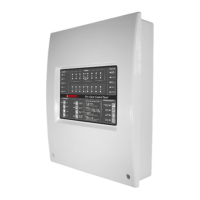
From detection zone output card
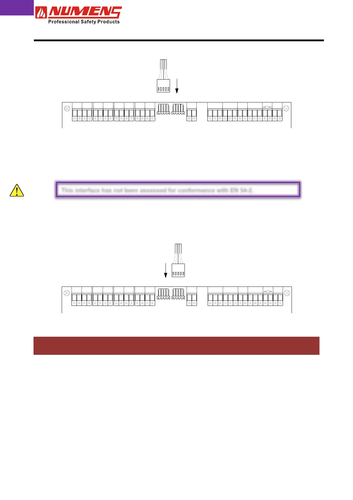
From repeater panel
6.13. Repeater Output
The repeater output connects to the 4001-04 8-zone Repeater Panel. The Repeater displays the status and
provides control of the fire detection and alarm system. The 6001-03 Network Interface Card must first be fitted
to the control and indicating equipment to provide the signaling interface to the Repeater Panels. The 4001
supports up to 7 Repeater Panels.
Connect the 6001-03 Network Interface Card to the DATA port on the main board, as shown below.
Install cabling from the 4001 Repeater Panel to the 6001-03 Network Interface Card. Terminate the wiring for
each indicator to their respective terminals, and the cable screens connected to earth.
7. PRE-COMMISSIONING
Prior to commissioning, undertake the following pre-commissioning checks.
1) Check the wiring for continuity. Short- or open-circuit indications must be rectified before connecting to the
control and indicating equipment. All cable testing must be carried out with a multi-meter, not a meg-ohm
meter when devices are connected. Induced voltages greater than DC 1 V indicates possible cable
problems or bad earth connection and must be rectified before device connection.
2) Check detection zone cables and ensure all field connections are made, and devices are connected to
their bases.
3) Check that all end-of-line devices are fitted, either to the last device on the detection zone circuit, the last
device on the alarm zone circuit, or to the output terminals (where the zone circuit is not used).
4) Check the earth connection is secure.
DATAMPX
Z1 Z2 Z3 Z4 Z6Z5 Z7 Z8 S1
C
AUX
NONC NC N O
FIRE
CC
FLT
NC DV
INPUTS
CDE
RESET AUX SP
MPX
AUX SPRESET
DE C
INPUTS
DVNC
FLT
CC
FIRE
NONCNC N O
AUX
C
S1Z8Z7Z5 Z6Z4Z3Z2Z1
DATA
This interface has not been assessed for conformance with EN 54-2.
 Loading...