4001 non-addressable control and indicating equipment
Installation and Service Manual
13
32-0002-r12_2018-09
© 2015 ~ 2018 Ambest Electronics (Ningbo) Co Ltd. All rights reserved.
All specifications and other information shown were current at the date of publication and subject to change without notice.
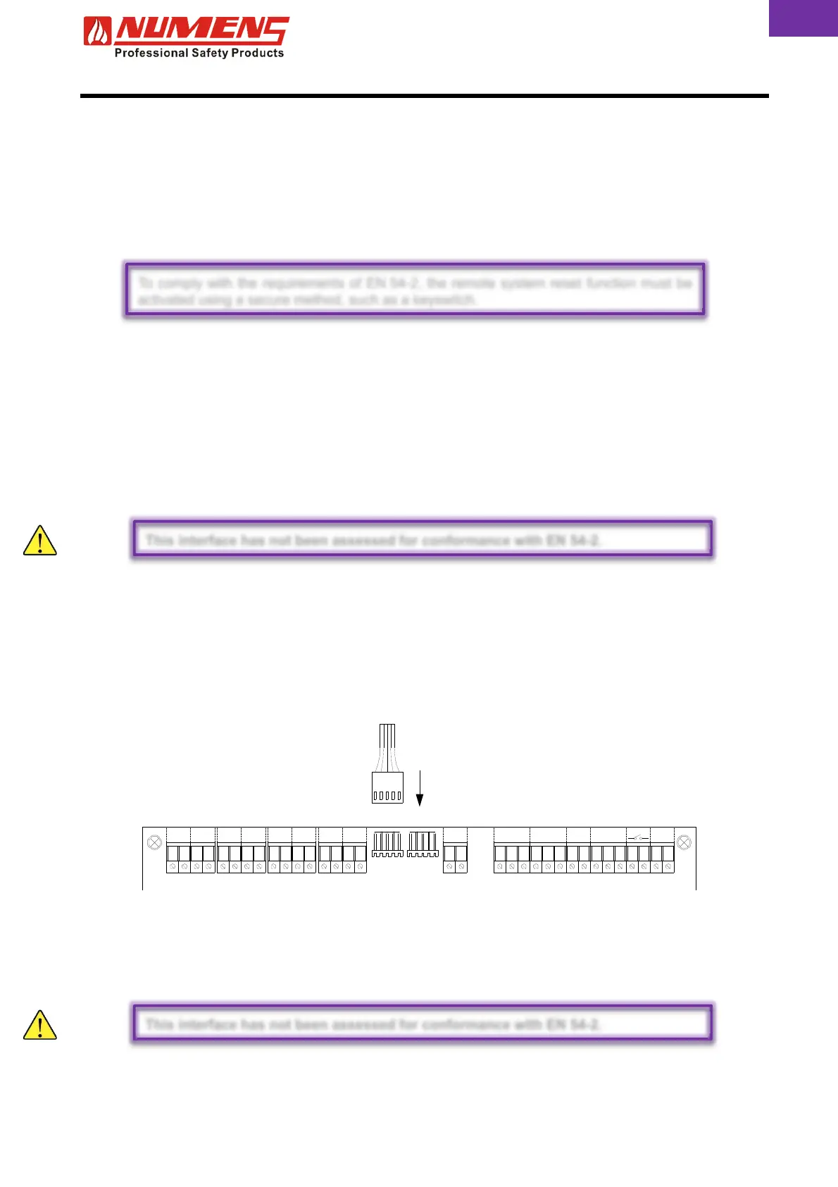
From remote display card
6.10. Ancillary Inputs
There are three remote activation inputs. All remote inputs are activated using a voltage free dry contact like
a relay. Terminate the wiring for each auxiliary input in their respective terminals and the cable screens
connected to earth.
6.10.1. Remote Reset
The momentary closure of a contact at remote reset input will initiate a system reset.
6.10.2. Evacuation Start/Stop
Evacuation Start/Stop activates alarms immediately when a short-circuit is applied to the input. The
SILENCE/ACTIVATE ALARMS LED will illuminate when active. Alarms continue to operate until the short-
circuit is removed, or the SILENCE/ACTIVATE ALARMS button is pressed.
6.10.3. Day/Night Mode
A short-circuit applied to the Day/Night Mode input will enable programmed delays (Day Mode). The DELAYS
ACTIVE LED will be illuminated. Removing the short-circuit will disable programmed delays (Night Mode).
6.11. Remote Display Output
Set the jumper on the 6001-04 Remote LED Display card to display Fire or Fault indications.
Set zone group jumper to A0 to display detection zones 1 ~ 8, or to position A1 to display detection zones
9 ~16.
Install the display card in a suitable enclosure or behind a protective panel.
Install cabling from the 6001-04 Remote Display card to the MPX port on the main board. Terminate the wiring
for each indicator to their respective terminals, and the cable screens connected to earth.
6.12. Detection Zone Output Card
The 6001-07 Detection Zone Output Relay card provides 8 voltage-free, normally-closed relay contact outputs
for detection zones. The relay contacts will open when a detection zone initiates an Alarm Condition.
Install cabling from the 6001-07 Detection Zone Output Relay card to the MPX port on the main board.
Terminate the wiring for each indicator to their respective terminals, and the cable screens connected to earth.
DATAMPX
Z1 Z2 Z3 Z4 Z6Z5 Z7 Z8 S1
C
AUX
NONC NC N O
FIRE
CC
FLT
NC DV
INPUTS
CDE
RESET AUX SP
To comply with the requirements of EN 54-2, the remote system reset function must be
activated using a secure method, such as a keyswitch.
This interface has not been assessed for conformance with EN 54-2.
This interface has not been assessed for conformance with EN 54-2.
 Loading...