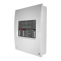
4001 non-addressable control and indicating equipment
Installation and Service Manual
2
32-0002-r12_2018-09
© 2015 ~ 2018 Ambest Electronics (Ningbo) Co Ltd. All rights reserved.
All specifications and other information shown were current at the date of publication and subject to change without notice.
2. OPTIONAL INTERFACES
The 4001 is compatible with the following optional equipment.
2.1. Remote LED Display
The 6001-04 remote LED display card is used to repeat the discrete Alarm or Fault LED indications of the
control and indicating equipment. Eight discrete LEDs can be configured to display zone Alarm or Fault
conditions.
2.2. Detection Zone Output Card
The 6001-07 Detection Zone Output card provides 8 voltage-free, normally-closed and normally-closed relay
contact outputs, available for detection zones. The relay contacts operate when a detection zone initiates an
Alarm Condition.
2.3. Repeater Panel
The 4001-04 Repeater Panel provides indication and control functions in a location separate to the control and
indicating equipment. The 4001 supports up to 7 Repeater Panels.
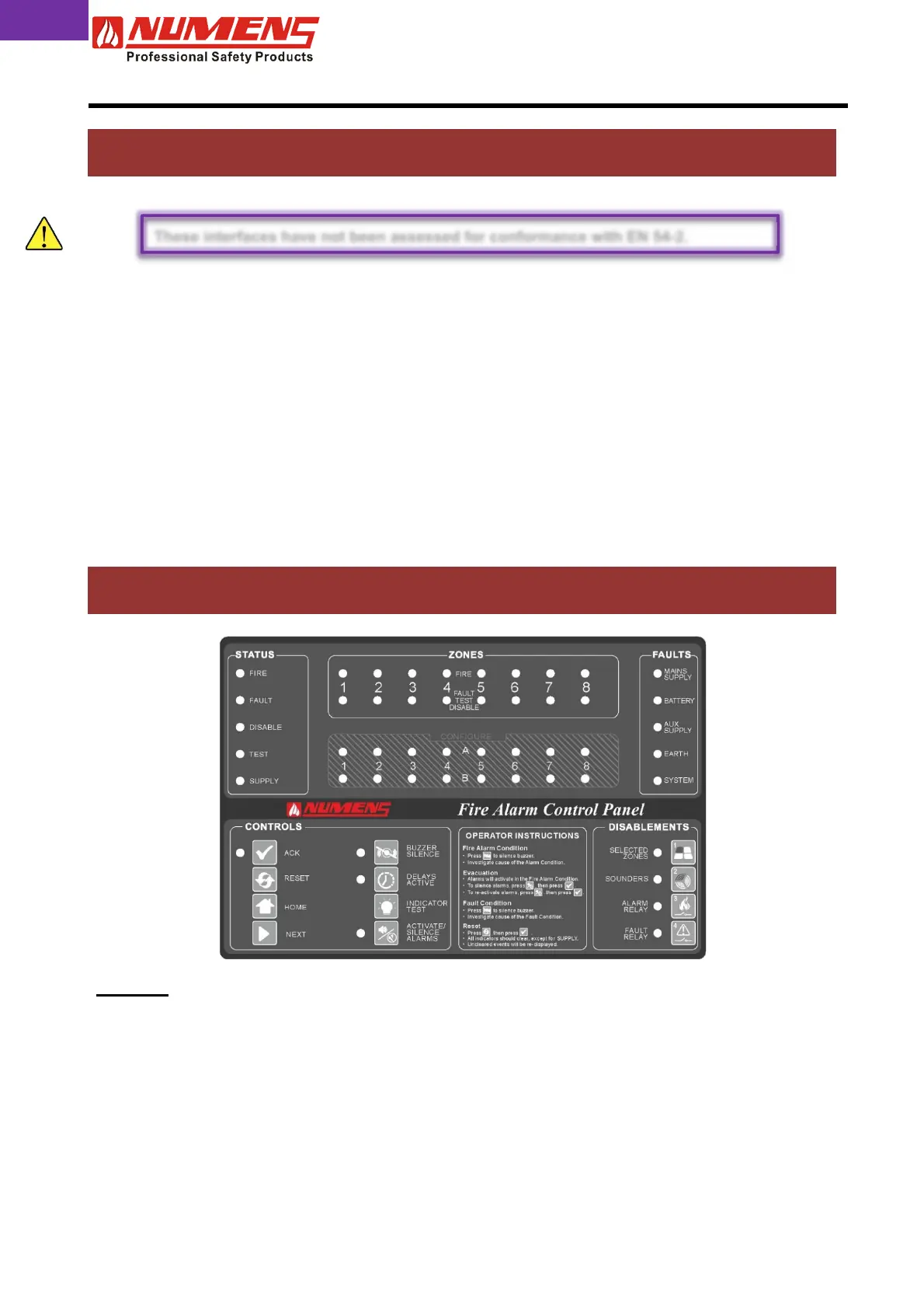
3. CONTROLS AND INDICATORS
STATUS
FIRE
Indicates the Alarm Condition. Alarm zone information will also be displayed on
the ZONE indicators.
FAULT Indicates the Fault Condition. Fault information will be displayed on the ZONES
indicators or in the FAULTS area of the control and indicating equipment,
depending on the source of the fault.
DISABLED Indicates at least one function (eg detection or Auxiliary Outputs) is disabled.
TEST Indicates the Test Condition.
SUPPLY Indicates the control and indicating equipment is active.
These interfaces have not been assessed for conformance with EN 54-2.
 Loading...