4001 non-addressable control and indicating equipment
Installation and Service Manual
11
32-0002-r12_2018-09
© 2015 ~ 2018 Ambest Electronics (Ningbo) Co Ltd. All rights reserved.
All specifications and other information shown were current at the date of publication and subject to change without notice.
6.4. Control and Indicating Equipment Power-Up
Before connecting external wiring, apply power to the control and indicating equipment with the end-of-line
devices for detection and alarm zones installed.
Depending on panel load and standby requirements, two DC 12 V valve-regulated lead-acid batteries with a
capacity up to 7 Ah may be fitted in the enclosure. The batteries should be wired in series (DC 24 V) using the
supplied link. Take care not to short circuit the battery terminals.
With mains and battery power connected, there should be no fault indications.
6.5. General Wiring Requirements
Wiring should be installed in accordance with National Standards and wiring regulations.
To protect against electrical interference the use of screened cables throughout the system is recommended.
Separate cables should be used for alarm and detection circuits, the use of multi-core cables to carry alarm
circuits and detector circuits is not recommended. The cable screens should be terminated and connected to
Earth at the panel only.
Maximum cross section of cables to use is 2.5 mm² to avoid damaging the terminals in the control and
indicating equipment.
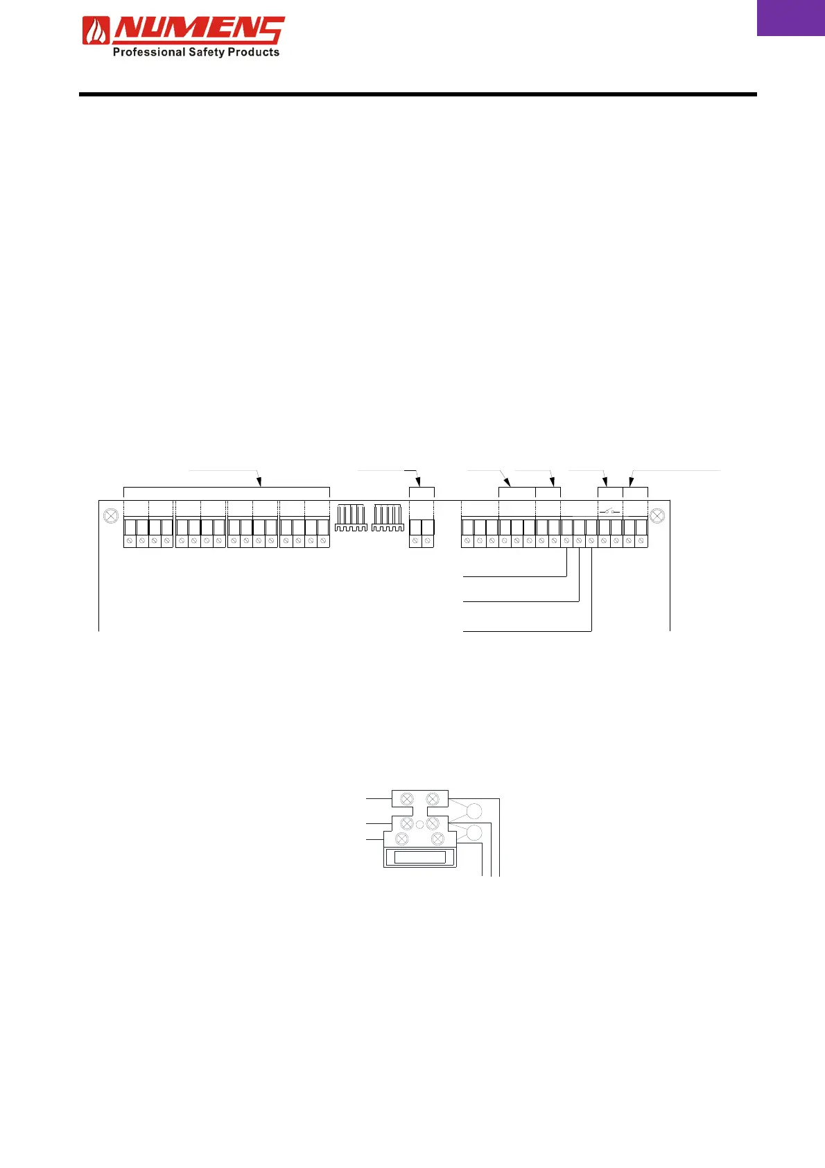
The input/output terminals are shown below.
6.6. Mains Wiring
Mains supply wiring should only be undertaken by a suitably qualified and competent person.
Mains wiring should be 3-core (1 ~ 2.5) mm², fed from a dedicated 3 A (or greater) circuit breaker. The circuit
should be secured from unauthorized operation and be marked “Fire Alarm Do Not Switch Off”.
The mains supply should be routed away from the other cables and enter the control and indicating equipment
adjacent to the Mains terminal block.
6.7. Detection Zones
Each zone has capacity for at least 32 devices. Alarm zone limitations may also be restricted by local
regulations.
A capacitor end-of-line device is supplied for each zone as part of the monitoring circuit. Fit the capacitor to
the last device of each Zone. If a zone is unused, fit the end-of-line capacitor to the zone terminals. If the
capacitor is not installed, a fault will be indicated for that zone.
A detector circuit wiring layout is shown below. Consult the device installation instructions for device
termination requirements.
Z1 Z2 Z3 Z4 Z6Z5 Z7 Z8 S1
C
AUX
NONC NC NO
FIRE
CC
FLT
NC DV
INPUTS
CDE
RESET AUX SP
Detection
Zone Inputs
Alarm Device
Output
Fire
Relay
Fault
Relay
Auxiliary Supply
Output (DC 24 V)
Remote
Reset
Day/Night Mode
Common
Evacuation on/off
MPX DATA
Neutral
Earth
Active
Fuse
 Loading...