Page 10 of 54
7. Opto encoder-printed circuit board
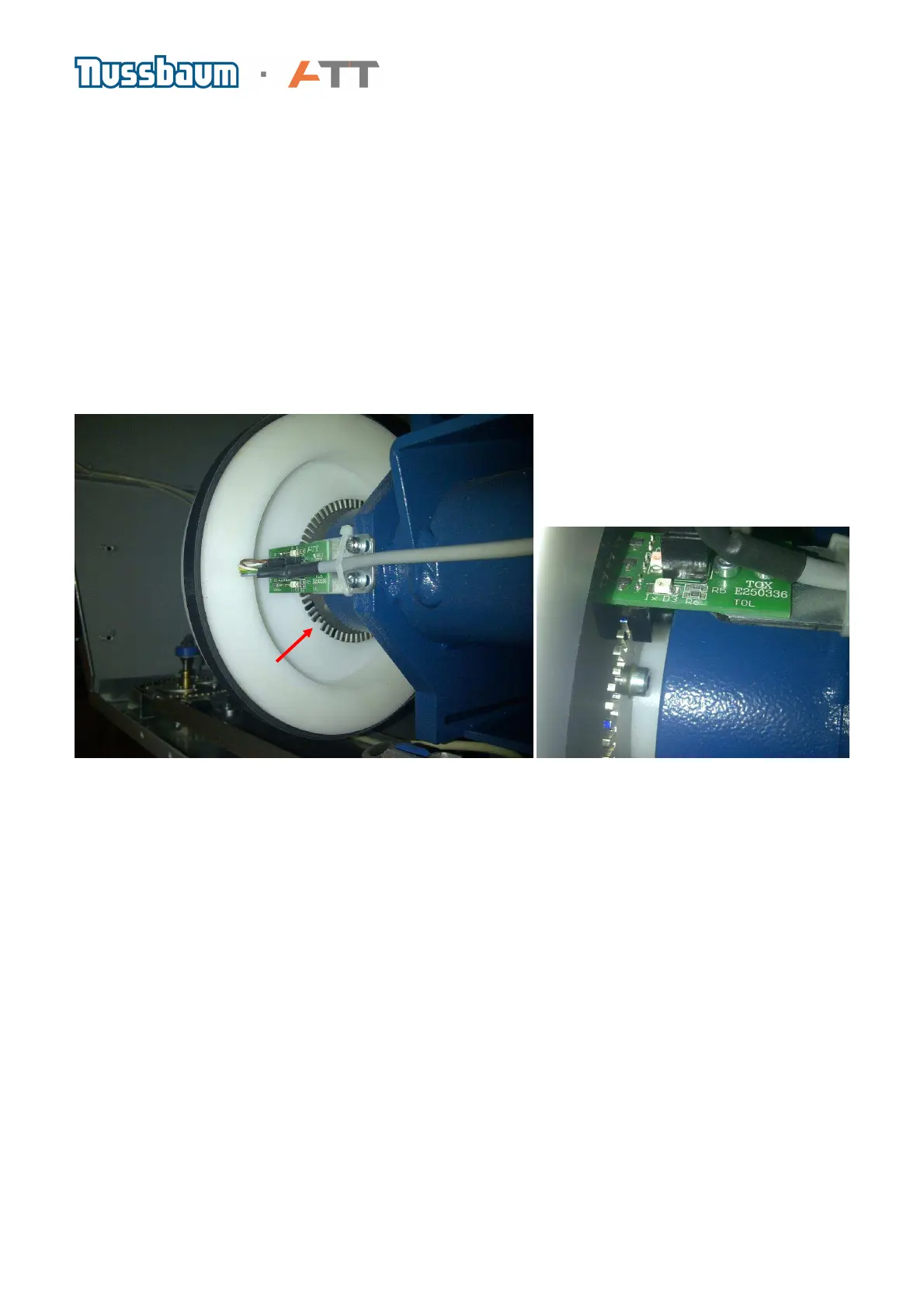
a) There are three red light diodes on the opto encoder printed circuit board. When these three
light diodes are blinking during the operation of the machine, it means the opto encoder is
functioning. If the machine is switched on (CAREFUL VOLTAGE) and the main shaft is turned
slowly, the blinking of the diodes can be observed.
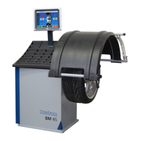
b) To remove, unplug the lead at J2 on the basis board. Loosen the securing screws (1) enabling
the metal support (2) with the opto encoder board to be withdrawn from the machine. Unscrew the
opto encoder board (3) from metal support and replace with another. Return metal support with
opto encoder into position and secure. The opto encoder board must not make any contact with
either the toothed disc (4) or the drive pulley (5). Finally re-connect the plug
c) Note: If a new opto encoder board has been fitted and the position for placing weights cannot
be found, then the actual angle of the opto encoder in relation to the toothed disc should be
checked. As seen in the upper picture, the sensor should be at 90° to the drive pulley
d) If you check the toothed disc, you will find a position where there is a small gap (See red arrow
in the picture above). This position is measured by the opto encoder as Zero point. The toothed
disc has 256 segments and by selecting function F9 on an LED machine you can see the number
of each segment as the main shaft is turned. With monitor machines, the same function can be
checked in the service screen reading from the bottom left of the screen. If the main shaft is
turned a complete revolution in a clock wise direction the scale will count from 0 to 255 and
likewise opposite in a counter clockwise direction.
 Loading...