Page 9 of 54
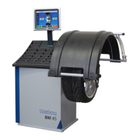
6. Piezo sensors
a) Disconnect the connecting lead J6 from the Basis board. Loosen the pies sensor securing nut
(1) and screw out the securing bolt (2) using an Allen key. Please note that on machines built from
August 2011 the screw of the sensor is secured inside the thread with Loctite
Look out for the four ball bearings (3) at either end of the piezo sensors. To replace the sensors,
first clean and then put a small dab of grease into the socket spaces for the ball bearings, clen the
thread from remaining Loctite, put medium type Loctite on the screw and place the Piezo sensor
gently into position.
Return each piezo sensor with the ball into position and screw on the sensor securing bolt making
sure that the ball is also in position. Tighten the securing bolt to 2Nm. Do not over tighten the
sensors and tighten the securing bolts alternately.
Replace the securing nut and finally re-connect the leads to the basis board at the point J6.
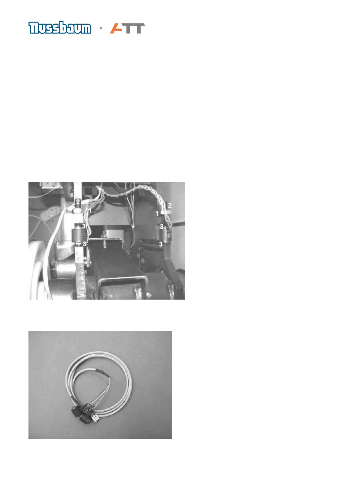
b) The piezo sensors always come as a set with balls and a single shared lead connecting to a
plug. They can be fitted in any position i.e. front, rear, left or right without any adverse affects on
results. After replacing the sensors, it is imperative that a zero run and calibration are carried out.
Photo shows Piezo sensors (Art.Nr. 1987009WH2A)
 Loading...