Page 11 of 54
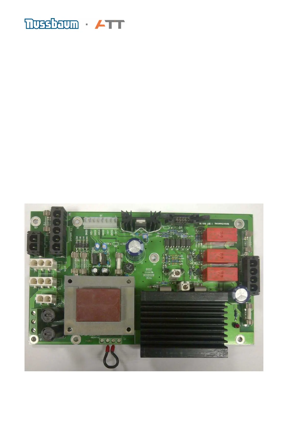
8. Motor control board
a) The motor controller board works in conjunction with the transformers (located on the lower
side of the board to make up the power supply for the balance machine. To remove the motor
controller board, unplug the connected cables and loosen the securing screws. Replace a new
board opposite to the method of removing.
b) Overview of the symbols printed next to the relevant connections:
J3 Control line basis board -> Motor controller board
J5 Bridge 115 V / 230 V input voltage
J6 Power supply to the basis board
X5 Mains supply
X4 Connection to primary side of transformer (located below motor control board)
X5 QuickSpan
X6 Connection to secondary side of transformer (located below motor control board)
X7 Motor and Brake
c) The red LED D1 indicates whether 24VDC or 48VDC is available. The LED will stay illuminated
even when the machine has been unplugged from the mains because the power supply unit
contains a filter capacitor. The light can also illuminate when the motor is turned as it acts like a
generator and so charges the capacitor with electricity simultaneously.
More information on fuses see chapter 22
 Loading...