Nuvoton Nu-Link Debug Adapter User Manual
Oct 24, 2019 - 17 - Revision V1.01
4 Installation and Setup
This chapter introduces how to connect the Nu-Link Adapter to a computer, and how to set the third-
party tool to use the Nu-Link Adapter as a debugger and a programmer.
4.1 Connecting to the Nu-Link Adapter
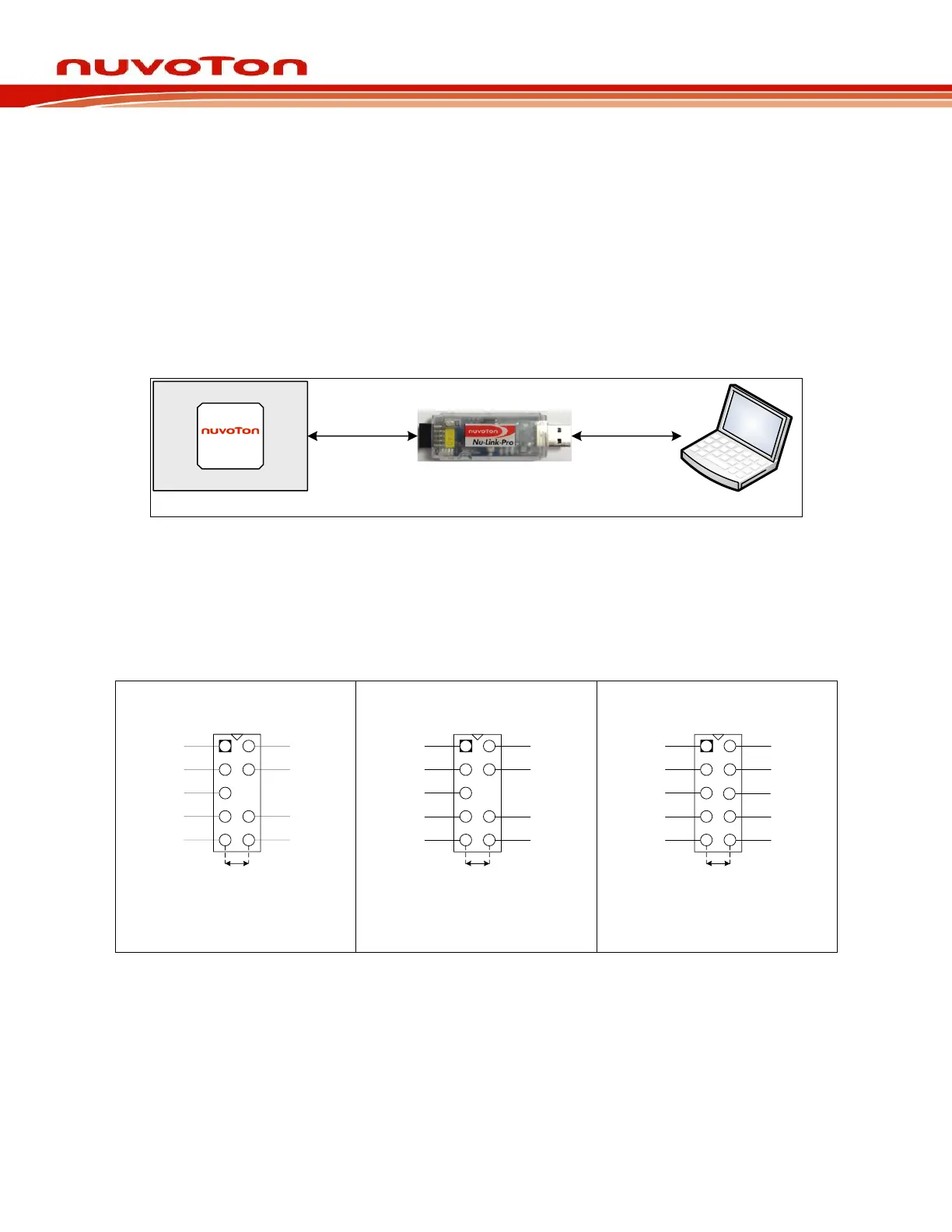
As shown in Figure 4-1, the Nu-Link Adapter is a bridge between an USB and the SWD interface, by
which software tools can debug and program the target chip through an USB. The user can plug the
Nu-Link Adapter into an USB port of a PC directly or connect using the USB connector.
Through a SWD port, the Nu-Link Adapter can supply power (1.8V, 2.5V, 3.3V, or 5.0V) to a target
circuit board. The maximum is 5V/500mA. Refer to Table 2-1 for detailed specifications.
Figure 4-1Nu-Link Adapter Connection Diagram
SWD Connector:
The SWD connector, which can be applied to all of the NuMicro
®
development tools and evaluation
boards, is a 100 mil (2×5) female header, as shown in the left of Figure 4-2.