Nuvoton Nu-Link Debug Adapter User Manual
Oct 24, 2019 - 4 - Revision V1.01
2 Hardware Specifications
The Nu-Link Adapter provides an USB connector and a SWD signal interface for connecting to the
target chip. The user can connect the Nu-Link Adapter to an USB port of a PC to debug and program
target chips through the development software tools. As shown in Table 2-1, there are three
specifications for the Nu-Link Adapter, in which debugging, Online/Offline Programming, and SWD I/O
voltage settings may be supported depending on the specifications (refer to the +Appendix for details).
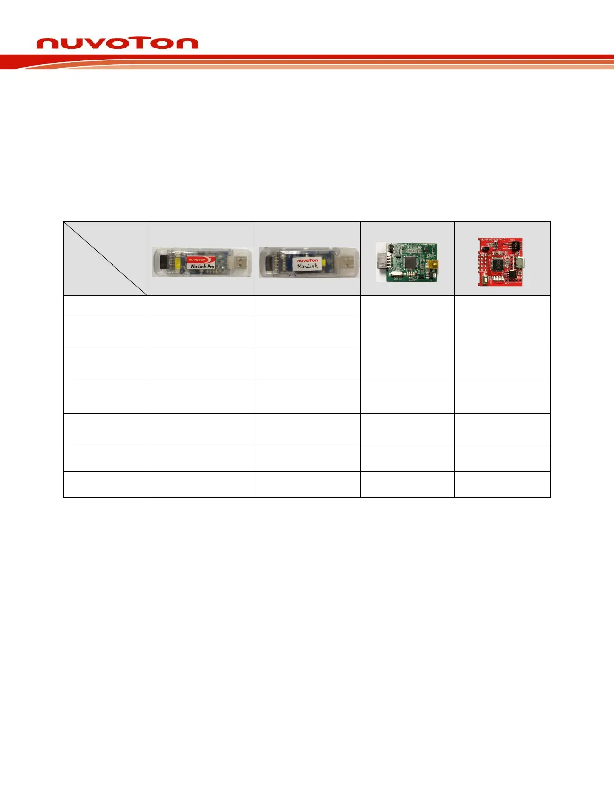
Table 2-1 Nu-Link Adapter Function Comparison
*
1
Adjusted by resistor JPR1.
*
2
Adjusted by resistor ICEJPR1.
*
3
The input supports 1.8V~5V, and the output only supports 1.8V~3.3V.
*
4
The Nu-Link2-Me can be connected to a automatic IC programming system through the control bus.
Control Bus for IC Programmer(Start, Busy, Pass, Fail) .
*
5
Virtual COM is supported in versions later than V3.0.
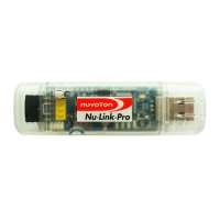
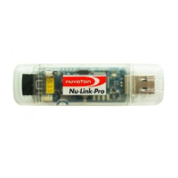
2.1 Nu-Link-Pro
The Nu-Link-Pro is a full-functional debugger and programmer with debugging, online/offline
programming, and SWD I/O voltage setting functions. As shown in Figure 2-1, the Nu-Link-Pro
includes an USB port that can be connected to a computer host, a set of Status LEDs, an offline
programming button, a SWD port that can be connected to a target chip for debugging and
programming (the voltage level of the SWD port can be adjusted through software as 1.8V, 2.5V,
3.3V, or 5.0V), a set of SWD I/O voltage LEDs and SWD Power Output LEDs.