Nuvoton Nu-Link Debug Adapter User Manual
Oct 24, 2019 - 32 - Revision V1.01
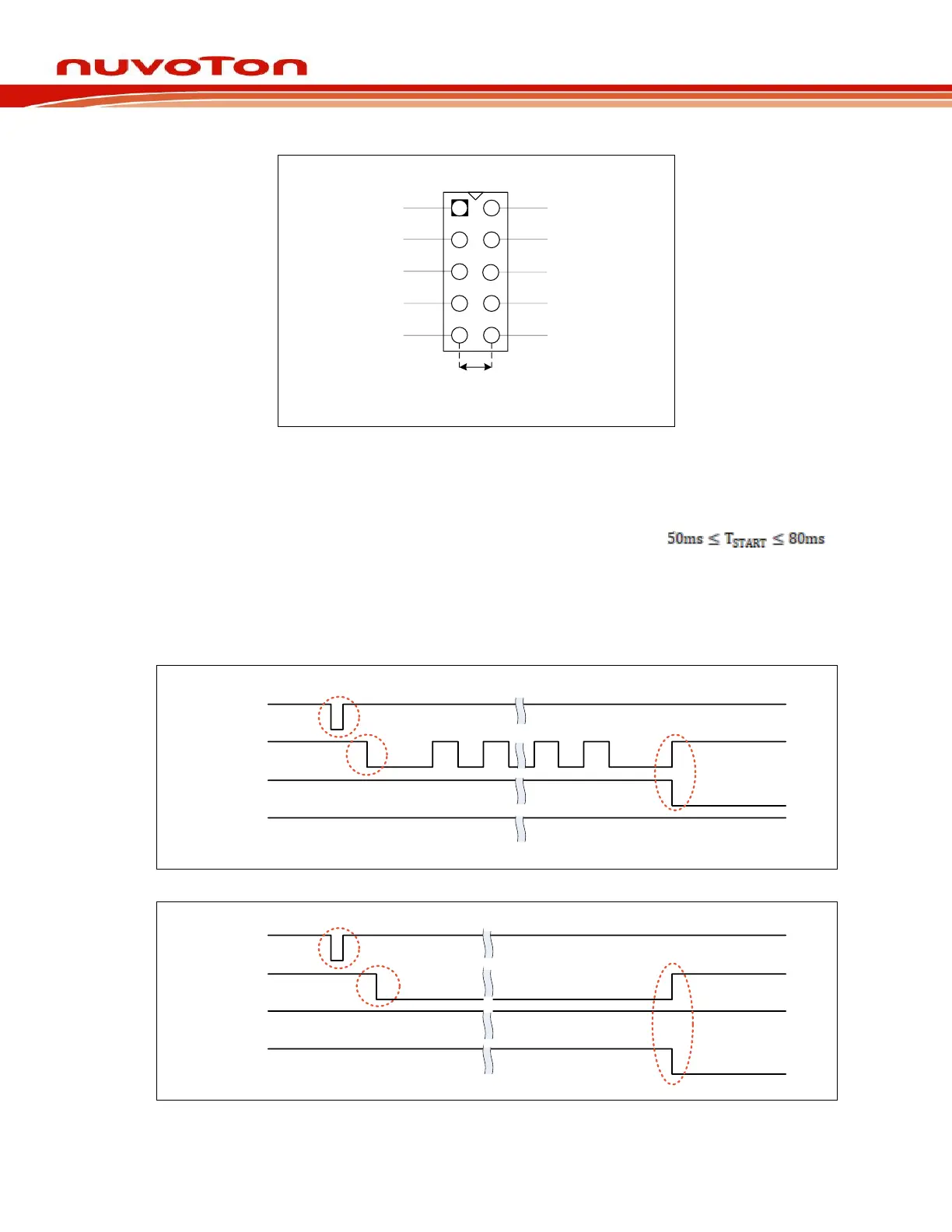
Figure 5-1 SWD Connector Pin Diagrams
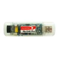
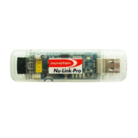
5.2.1 Operation sequence and Waveform
1. The Nu-Link2-ME power on. START, BUSY, PASS, and FAIL are set to logic.
2. To start programming, START needs to be set to logic 0 for TSTART,
3. Programming start-up. BUSY is set to logic 0, and might toggle during programming.
4. When finish programming, BUSY is set to logic 1, and PASS or FAIL is set to logic 0.
When BUSY is set to logic 1, and PASS is set to logic 0, means “PASS”.
When BUSY is set to logic 1, and FAIL is set to logic 0, means “FAIL”.