83
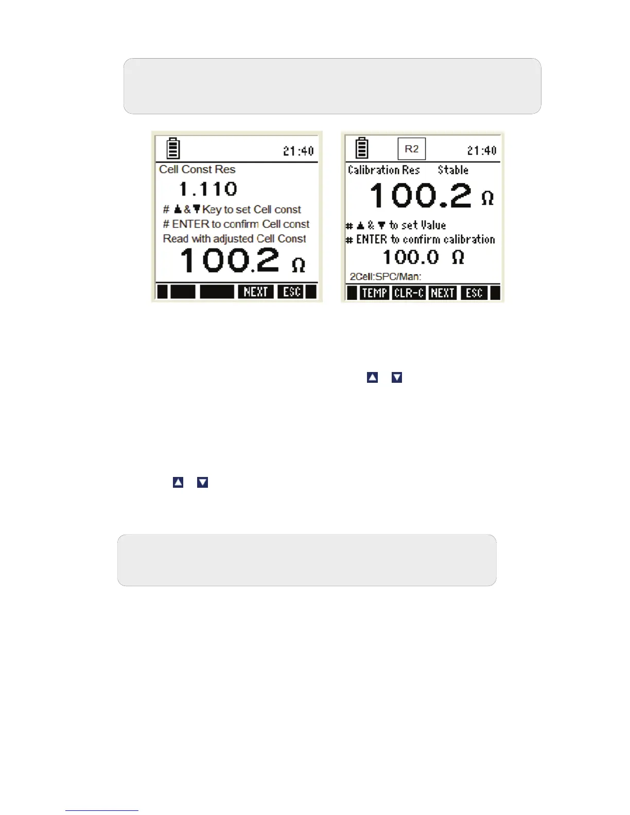
Figure 40 : Resistivity Cell constant & resistivity calibration
4. The upper display of the resistivity cell constant screen shows the cell
constant of your cell & lower display shows the measured value of the
solution with adjusted cell constant. Press & keys to adjust the cell
constant for your custom solution in upper display.
5. Press ENTER key to confirm the entered value and to go to resistivity
calibration screen.
6. The screen shows two readings. The upper display shows the resistivity
reading of the solution with respect to previous calibration (if any) & lower
display shows the resistivity reading of the solution without any calibration.
Use
& keys to adjust the upper display of the resistivity value of your
custom solution.
7. Press ENTER key to confirm the entered value.
8. Rinse the probe with de-ionized water. Place it in the next solution and
follow the steps 2 to 7 to calibrate other points, if ‘MULTI’ point calibration
is selected.
9. Press ESC (F4) to go to measurement mode. The meter shows the
resistivity reading of the solution in measurement mode.
2.1 Resistivity Calibration Report
Calibration report gives you information on calibration. It includes date &
time of calibration and the cal factor.
Note: If the meter is password protected, you will be prompted to enter a
password.
Note: The function of the keys available on the resistivity cell
constant/calibration/ report screen is the same as previously
described in conductivity calibration.


 To Next Page