—
""
T,*,V,—ITfl-^^rv^-j
'irawrmr
|J "^
Single Patch Pages
The Xpander voice can
be
divided
into two
parts:
The HARDWARE part
is
the section that
actually produces the sound
—
the oscillators,
filter,
and output
amplifiers (VCAs
1
&
2).
These elements are always part of
every
patch,
in the
same
configuration.
Obviously,
the
frequencies, waveshapes, filter modes and levels can be adjusted, but the
configuration
always stays
the same.
The
SOFTWARE
part contains
the
elements
that control
the hardware. These elements
make no sound of their own. but are what provide the
Xpander with its unparalleled
flexibility.
The Xpander's software
elements include the LFOs.
Envelopes, Tracking Generators.
Ramps, and
Lag
Processor,
as
well as the interpreter for the
Control Voltage
inputs, and the
MIDI input which besides pitch also carries Velocity.
Pressure. Pitch Bend,
Vibrato, and
other
controller information
These software elements
can
be
arranged in any
order or configuration, and can be set to
control each other or even themselves This
flexibility is achieved
through Oberheim's Matrix
Modulation" control system An analogy to the
Matrix Modulation system
might be all of
those
millions
of
wires that existed on the first modular synthesizers As
cumbersome as
all
of that wiring was,
it
allowed the user to
connect any input to any output,
resulting in sophis-
tication and flexibility
unmatched
by
any programmable synthesizer, .until
now. Because
all
of the
modulation devices are in software, we can use "software
wiring"
to
connect one
module to another and
have the computers remember it
all.
By
the way. throughout
the Xpander and in this manual, we
have
used
familiar names for
familiar functions, for example VGA (Voltage
Controlled Amplifier). Most of the 90 VCAs
in
the
Xpander exist only
as
numbers in the computer
program,
and the
18 VCAs that physi-
cally exist in
hardware
are
controlled
by
voltages generated
by a
computer. Yet the VCAs
in
the
Xpander
have the same functions as those
in earlier synthesizers, so we discuss them
in
the
same terms.
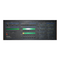
There are nine main Single Patch Pages. These are
selected with the nine buttons within the
block diagram on the
right
side of the
front panel
When one of the Single Patch Pages is selected, the LED
next
to
the button in the block dia-
gram will light and the name of the
page
will
appear
on the "current
page"
section
of the
Programmer display. The functions associated with this page
are displayed on
the Page
Modifier
displays.
tmrm
,ra l^ iiiif
22 Xpander
Owners Manual
Crea'ivo
input/
'"'
he
Xpanced Voice

 Loading...