Patent No. 6,766,028 - OFI Testing Equipment, Inc.
OFITE, 11302 Steeplecrest Dr., Houston, TX 77065 USA / Tel: 832-320-7300 / Fax: 713-880-9886 / www.ote.com 8
Setup
The Model 900 Viscometer is a precision instrument. Any damage to the bob
shaft, bearings, or transducer will greatly affect the accuracy of the readings.
Always handle the Viscometer with care, especially when installing and
removing the bob.
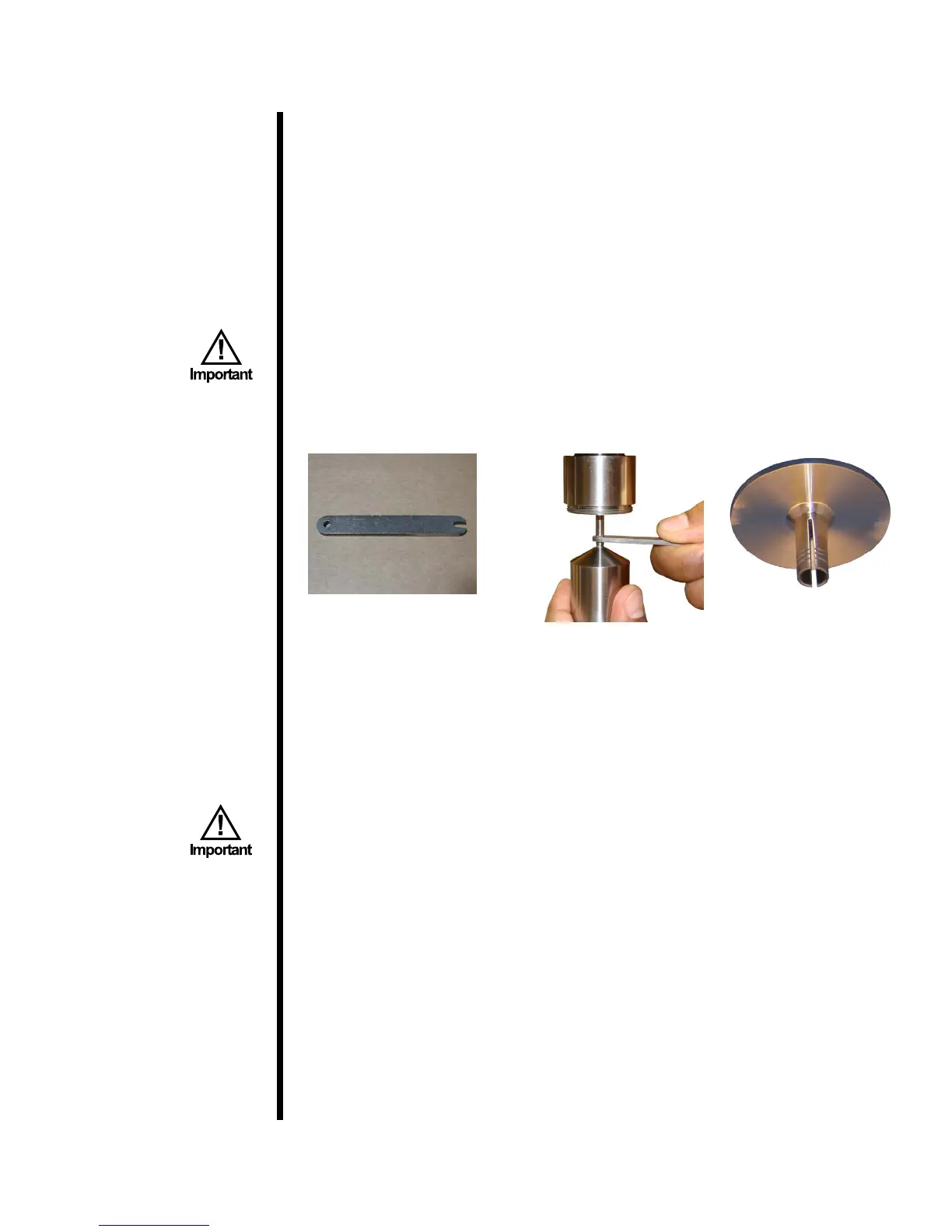
1. To install the bob, rst slide the bearing shield (#132-57) onto the bob
shaft with the at portion facing up. Locate the wrench ats on the bob
shaft. Place the bob shaft wrench (#130-76-08) against these ats to hold
the shaft in place. Tighten the bob by turning it clockwise (when viewed
from above).
Always use the bob shaft wrench when installing or removing the
bob. Do not tighten the bob against the stop pin.
If the bob or spring is being changed, run the TransCal procedure (steps
10 – 14 on page 51).
Bob Shaft Wrench
(#130-76-08)
Bearing Shield
(#132-57)
2. Some viscometers are equipped with a magnetic KlikLock™ bob. To
install this bob, slide it up into the rotor and turn it just until it clicks into
place.
3. Connect the instrument to a power source. This viscometer will operate
equally well at 115 Volts or 230 Volts, 50 or 60 Hz.
Always plug the Model 900 into a surge suppressor instead of
directly into an electrical outlet. The internal electrical components
can be damaged by voltage spikes.
4. To control the temperature, plug the thermocouple into the left side of the
housing cover and place the thermocouple into the thermocouple well of
the heat cup. Also plug the power cord of the heat cup into the back of
the Model 900. Turn the knob on the heat cup all the way to maximum to
allow the viscometer to control the temperature.