
S
Stacey CalderonSep 6, 2025
What is EEP Error on OHAUS Accessories?
- SsmithheatherSep 6, 2025
The EEP Error on OHAUS Accessories indicates a corrupted EEPROM data.
What is EEP Error on OHAUS Accessories?
The EEP Error on OHAUS Accessories indicates a corrupted EEPROM data.
What does NO.SW mean on my OHAUS Accessories?
If your OHAUS Accessories displays ‘NO.SW’, it means you are attempting to exit the menu with the LFT setting ON and the security switch OFF. Set the security switch to the ON position.
What does REF WT Err mean on my OHAUS Accessories?
If your OHAUS Accessories displays ‘REF WT Err’, the reference weight is too small. Use a greater weight for the sample.
What to do if my OHAUS Accessories unit will not turn on?
If the OHAUS Accessories unit does not turn on, first check the power cord connections to ensure it is properly plugged into both the unit and a functioning power outlet. Verify the power source is supplying electricity. If using a T52P model, the batteries may be discharged and need replacement. If these steps don't resolve the issue, service is required.
What does it mean when the battery symbol is flashing on my OHAUS Accessories?
If the battery symbol is flashing on your OHAUS Accessories (T52P), it indicates that the batteries are discharged and need to be replaced.
How to change menu settings on my OHAUS Accessories?
If you cannot change menu settings on your OHAUS Accessories, it is likely that the menu has been locked. To unlock it, set the selected menu to Off in the Lock Menu. Additionally, the Lockout Switch on the circuit board may need to be set to the Off position.
How to display weight in the desired weighing unit on my OHAUS Accessories?
If your OHAUS Accessories cannot display weight in the desired weighing unit, the unit may not be set to On in the Units Menu. Enable the unit in the Units Menu.
What to do if my OHAUS Accessories scale cannot zero?
If the OHAUS Accessories scale cannot zero, or will not zero when turned on, it may be due to the load on the scale exceeding allowable limits, the load not being stable, or load cell damage. Remove the load from the scale and wait for it to become stable. If the problem persists, service is required.
Why am I unable to calibrate my OHAUS Accessories?
If you are unable to calibrate your OHAUS Accessories, it might be because the Lock Calibration Menu is set to On, or the LFT menu is set to On, or you are using an incorrect value for the calibration mass. Set the Lock Calibration Menu to Off and the LFT menu to Off. Ensure you are using the correct calibration mass.
What to do if my OHAUS Accessories shows Error 9.5?
If the OHAUS Accessories scale displays Error 9.5, it indicates that calibration data is not present. You should calibrate the scale.
| Display | LCD |
|---|---|
| Protection | IP54 |
| Legal for Trade | Yes |
| Calibration | External Calibration |
| Power Supply | AC Adapter |
| Dimensions | 300 x 300 x 120 mm |
| Communication | RS232 |
| Operating Temperature | 0 to 40 °C |
| Relative Humidity | 10% to 85% non-condensing |
General safety guidelines for operating the equipment safely and reliably.
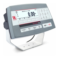
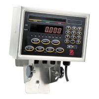
Identification and description of the indicator's physical components and controls.
Explains the purpose and action of each button on the indicator's control panel.
Instructions for removing the indicator and its accessories from the packaging.
Details on connecting the scale base, power, and communication interfaces externally.
Procedures for opening the housing and making internal connections like load cell and SD card.
Guidance on orienting the rear housing of the TD52XW model for mounting.
Instructions and specifications for installing the mounting bracket.
An overview of the indicator's menu hierarchy and available settings categories.
Step-by-step guide on how to navigate through the indicator's menus and change settings.
Details on performing zero, span, linearity, and GEO calibrations for accurate measurements.
Configuration options for units, range, capacity, language, and power-on settings.
Settings related to the display's appearance and behavior, including stability and contrast.
Configuration of digital inputs and outputs for interfacing with external devices.
Selection and configuration of various units of weight for measurement.
Settings for Good Laboratory Practice (GLP) and Good Manufacturing Practice (GMP) data logging.
Configuration of serial, Ethernet, Wi-Fi, and Bluetooth communication parameters.
Settings related to the maintenance menu and service information.
Options for locking specific keys on the control panel to prevent unauthorized access.
Instructions for performing basic weighing operations, including application setup and tare functions.
Procedures for using the counting application, including setting average piece weight (APW).
Steps for performing checkweighing and check counting operations with defined limits.
Guide for setting up and performing percent weighing using a reference weight.
Instructions for performing dynamic weighing operations with different start/reset modes.
Lists OHAUS and MT-SICS commands for serial communication and data control.
Details the pinout and function of the RS232 connector for data communication.
Steps for establishing serial communication between the indicator and a computer.
Instructions for connecting the indicator to a serial printer for data output.
Describes the format and content of printouts for weighing and check applications.
Provides examples of printout configurations and data fields.
Information on managing the library of records stored on the Micro SD card.
Details on user profiles, login, and management of user accounts on the SD card.
Functionality related to Alibi memory for data integrity and record keeping.
Steps for configuring the indicator for legal for trade requirements.
Procedures for verification by authorized personnel to ensure compliance.
Methods for applying security seals to prevent tampering with settings.
Instructions for cleaning the T52P model indicator housing and control panel.
Instructions for cleaning the TD52XW model indicator housing and control panel.
A table listing common symptoms, probable causes, and solutions for troubleshooting errors.
Contact information and procedures for obtaining technical support and service.
Detailed technical specifications for the indicator models, including materials and ambient conditions.
List of available accessories and optional kits for the indicator.
Technical drawings showing the physical dimensions of the indicator models.
A table providing GEO codes for various geographical locations.
Appendix containing details on standard continuous output format and data byte definitions.
Appendix listing MT-SICS commands for controlling the indicator.