7.
Connection Diagram
43984801TH Rev.1
131 /
Oki Data CONFIDENTIAL
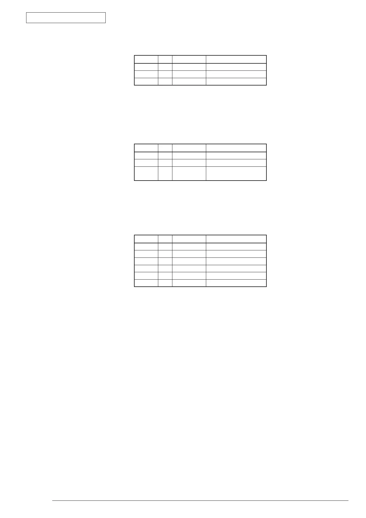
Pin No. I/O Signal Function
1 O FANPOW FAN Drive Power
2 C FANGND Frame Ground
3 I FANALM-P FAN Alarm Detection
• CN1 Connector Pin Allocation
(Connection to FAN)
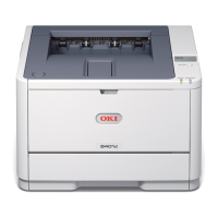
• CN2 Connector Pin Allocation
(Connection to the Fusing Thermistor)
Pin No. I/O Signal Function
1 O +5V Sensor Power
2 - NC Not Connected
3 I THERM Fusing Temperature
Detection
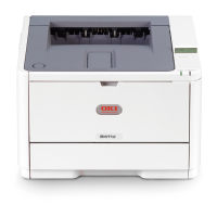
• CN4 Connector Pin Allocation
(Connect to Cover open switch / Toner TAG)
Pin No. I/O Signal Function
1 I H5V Cover Open
2 - NC Not Connected
3 O +5V Logic Power
4 I/O 1-WIRE EEPROM 1-wire signal
5 C GND Frame Ground
6 O FUSECUT Fuse-Cut Signal