7.
Connection Diagram
43984801TH Rev.1
133 /
Oki Data CONFIDENTIAL
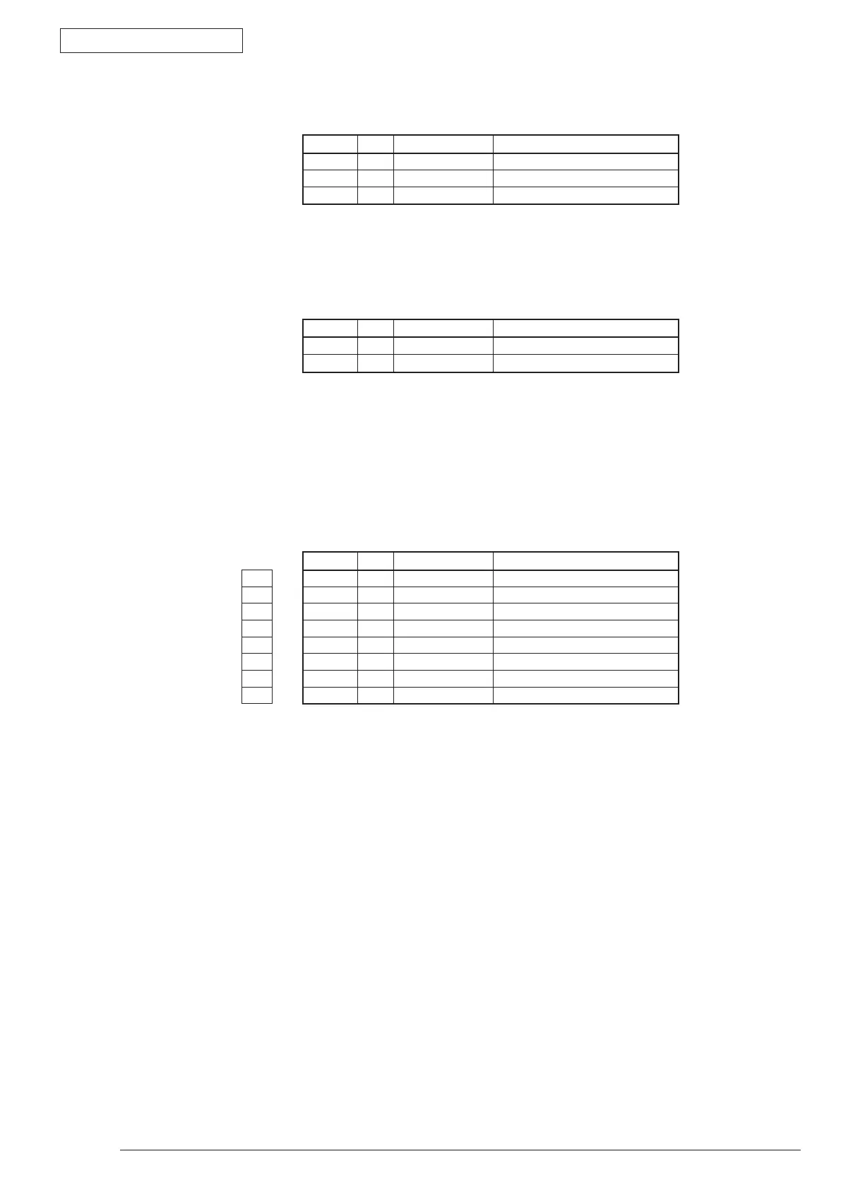
Pin No. I/O Signal Function
1 - AC(LIVE) FAN Drive Power
2 NC - Blank
3 - AC(NEUTRAL) Fan Alarm Detection
• CN1 Connector Pin Allocation
(Connection to the Fusing AC Supply)
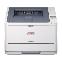
• CN2 Connector Pin Allocation
Pin No. I/O Signal Function
1 -
2 -
*When shoring out, it responds to 110v power voltage, and if it is
open, it responds to 220V.
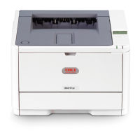
• CN3 Connector Pin Allocation
(Connection to the Main Control Board)
Pin No. I/O Signal Function
1 1 I HEATON-N Heater ON
2 2 O +5V Logic Circuit Power Supply
3 3 O +5V Logic Circuit Power Supply
4 4 C GND Logic Ground
5 5 C GND Logic Ground
6 6 O ZCROSS AC Zero Cross Signal
7 7 C 0VP Analog Ground
8 8 O +24V Motor/ Fan/ Clutch Drive Power