Appendix B USB Interface
43984801TH Rev.1
144 /
Oki Data CONFIDENTIAL
Note! The EOP width is defined by the bit time for a device type of the device receiving EOP.
The bit time is an approximate value.
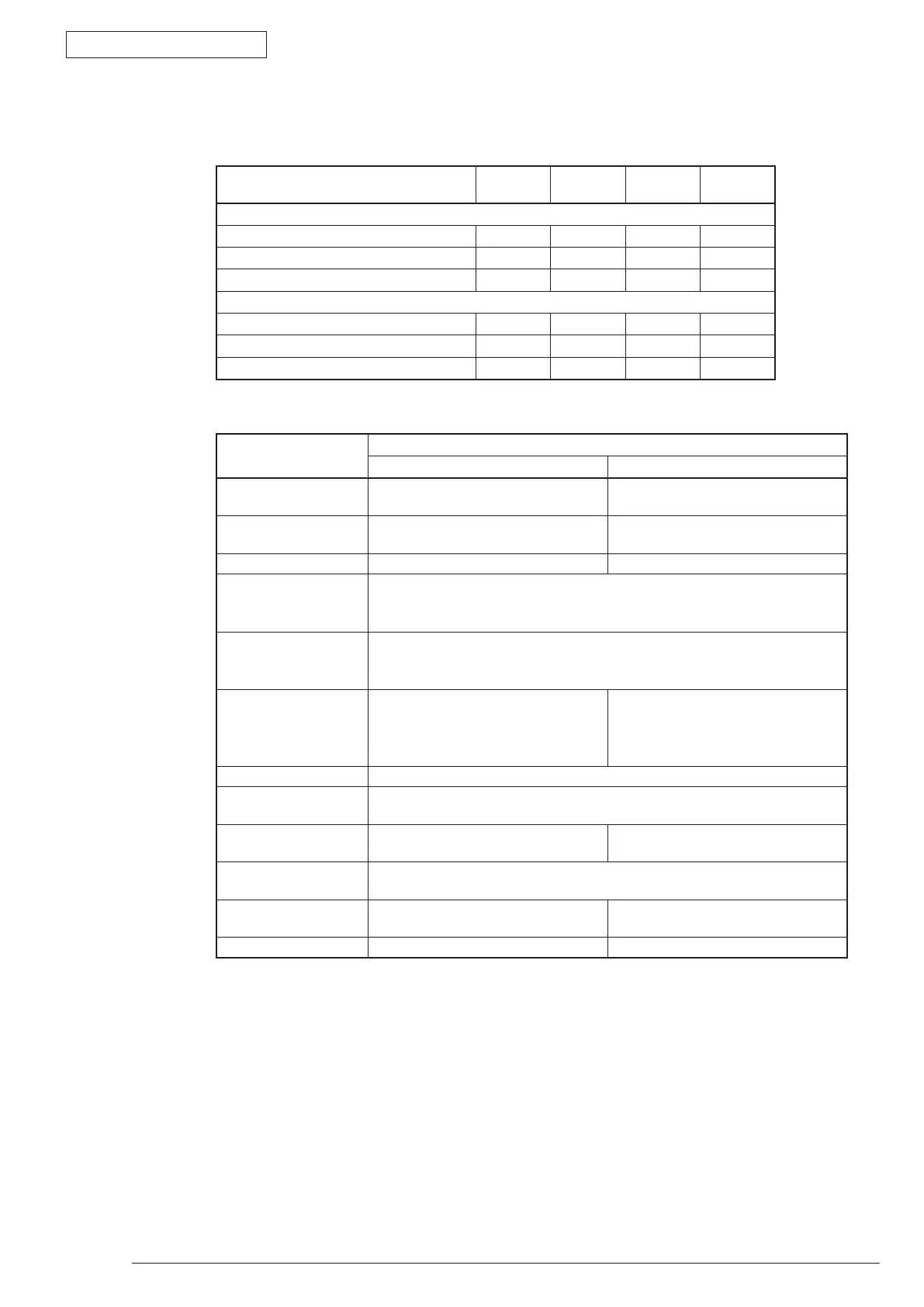
(8) Signal Level
• Input and Output Level
• Signal level
Parameter Signal Minimum Maximum Unit
Input level:
High (Driven) VIH 2.
0 V
High (Floating) VIHZ 2.7 3.6 V
Low VIL 0.
8 V
Output level:
Low OL 0.0 0.3 V
H
igh (Driven) OH 2.8 3.6 V
O
utput signal crossover voltage VCRS 1.3 2.0 V
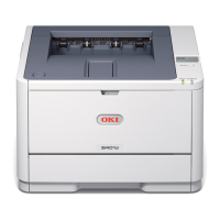
Bus Status
Signal Level
Request Acceptance
Difference "1" (D+) - (D-) > 200mV and D+ >
VIH (Min.)
(D+) - (D-) > 200mV
Difference "0" (D-) - (D+) > 200mV and D- >
VIH (Min.)
(D-) - (D+) > 200mV
Single-ended 0 (SE0) D+ and D- < VIL (Max.)
D+ and D- < VIH (Min.)
Data J state:
Low speed
Full speed
Difference "0"
Difference "1"
Data K state:
Low speed
Full speed
Difference "1"
Difference "0"
Idling State
Low Speed
Full Speed
D-
> VIHZ (Min.) and D+ < VIL (Max.)
D+ > VIHZ (Min.) and D- < VIL (Max.)
D- > VIHZ (Min.) and D+ < VIH (Min.)
D+ > VIHZ (Min.) and D- < VIH (Min.
Restart State Data K State
Start of the packet
(SOP)
The data line switches from the idling to the K state
End of the Packet
(EOP)
≧
SEO of 1 bit time, and then, J state
of I bit time
1
≧
SEO of 1 bit time, and then, J
state.
Not connected
(Downstream port)
SEO in
≧
2.5μs
Connected
(Downstream port)
Idling in
≧
2.5μs Idling in
≧
2.5μs
Reset In
≧
10ms, D+ and D- < VIL (Max.) In
≧
2.5μs, D+ and D-
<
VIL (Max.)