Appendix C Maintenance Manual for Second Tray unit
43984801TH Rev.1
164 /
Oki Data CONFIDENTIAL
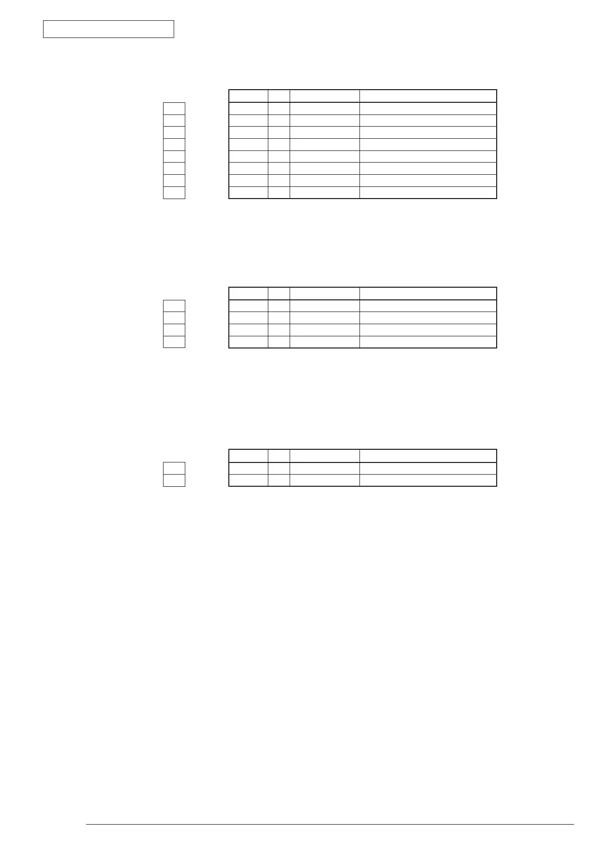
•CN1 Connector Pin Allocation
(Connection to the Main control board)
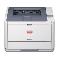
•CN2 Connector Pin Allocation
(Connection to the pulse motor)
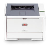
•CN3 Connector Pin Allocation
(Connected to Hopping clutch.)
PIN No. I/O Signal Function
1 1 I SCLK-N Clock
2 2 I/O DATA-N Data
3 3 O SDP-N OPT Transmission Mode
4 4 I OPCNT-N Control Signal
5 5 C 0V Logic Ground
6 6 I +5V Logic Circuit Power supply
7 7 C 0VP Analog Ground
8 8 I +24V Motor/ Clutch Drive Power
PIN No. I/O Signal Function
1 1 O HOP1 Motor Drive Power
2 2 O HOP2 Motor Drive Power
3 3 O HOP3 Motor Drive Power
4 4 O HOP4 Motor Drive Power
PIN No. I/O Signal Function
1 1 O HCLTON-P Clutch Drive Power
2 2 C HCLTGND Analog Ground