Distributor of Olimex LTD: Excellent Integrated System Limited
Datasheet of LPC-P11C24 - DEV BOARD FOR LPC11C24 CORTEX M0
Contact us: sales@integrated-circuit.com Website: www.integrated-circuit.com
OLIMEX© 2012 LPC-P11C24 user's manual
CHAPTER 6: CONNECTORS AND PINOUT
6. Introduction to the chapter
In this chapter are presented the connectors that can be found on the board all together with their
pinout and notes about them. Jumpers functions are described. Notes and info on specific
peripherals are presented. Notes regarding the interfaces are given.
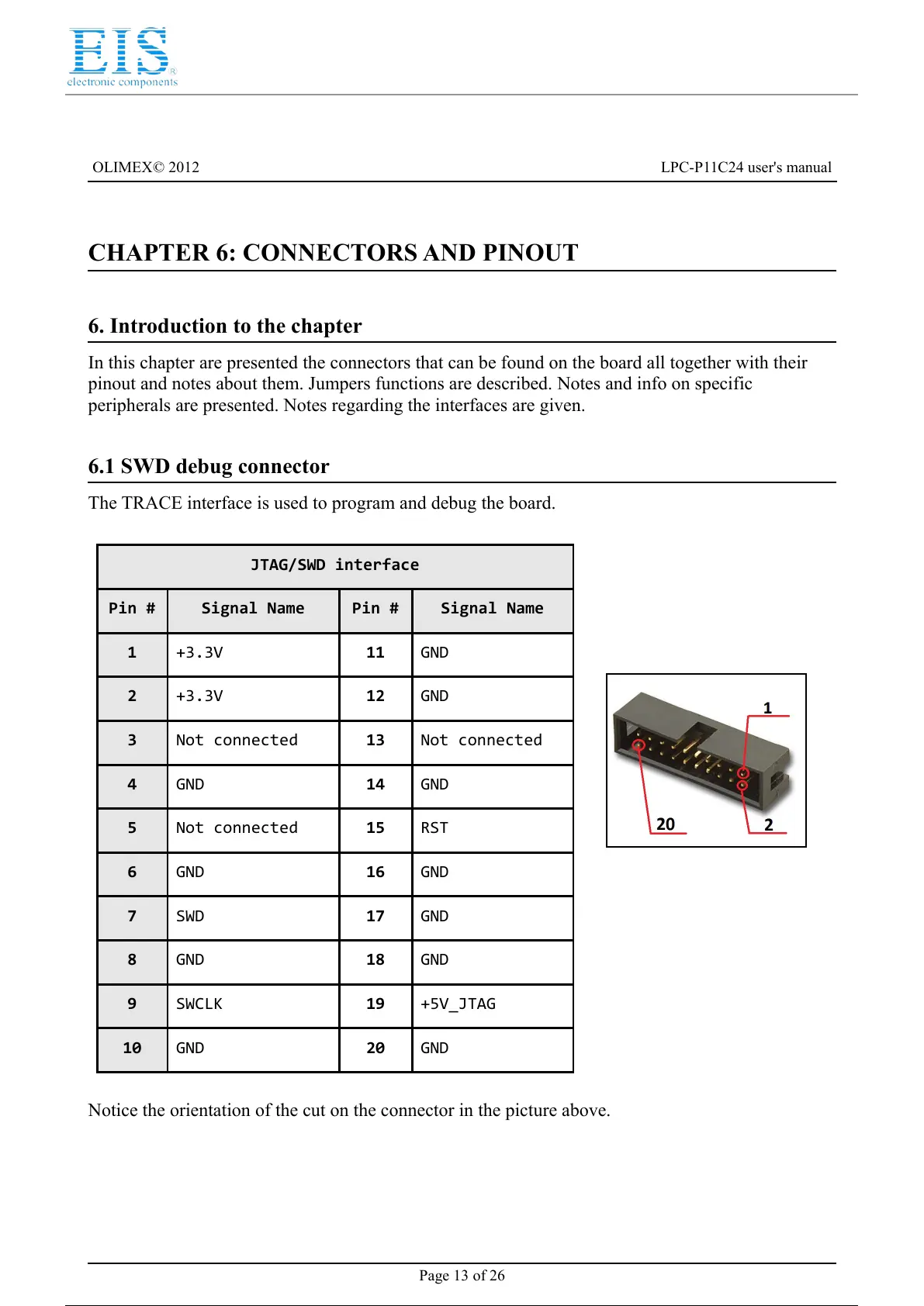
6.1 SWD debug connector
The TRACE interface is used to program and debug the board.
JTAG/SWD interface
Pin # Signal Name Pin # Signal Name
1 +3.3V 11 GND
2 +3.3V 12 GND
3 Not connected 13 Not connected
4 GND 14 GND
5 Not connected 15 RST
6 GND 16 GND
7 SWD 17 GND
8 GND 18 GND
9 SWCLK 19 +5V_JTAG
10 GND 20 GND
Notice the orientation of the cut on the connector in the picture above.
Page 13 of 26