Distributor of Olimex LTD: Excellent Integrated System Limited
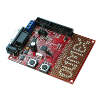
Datasheet of LPC-P11C24 - DEV BOARD FOR LPC11C24 CORTEX M0
Contact us: sales@integrated-circuit.com Website: www.integrated-circuit.com
OLIMEX© 2012 LPC-P11C24 user's manual
CHAPTER 5: CONTROL CIRCUITY
5. Introduction to the chapter
Here you can find information about reset circuit and quartz crystals locations, the power supply
circuit is discussed.
5.1 Reset
LPC-P11C24's reset circuit includes R49 (33Ω), R48 (10kΩ), and a RESET button.
5.2 Clocks
12 MHz quartz crystal Q1 is connected to pins 6 and 7 of the LPC11C24 processor.
5.3 Power supply circuit
The power supply circuit of LPC-P11C24 allows flexible input supply from 7V to 9V. This means a
wider range of power supplies, adapters, converters are applicable. The maximum amperage
recommended is 1A by default.
After initial power-up the board consumes 40mA @ 9V.
Page 12 of 26