Distributor of Olimex LTD: Excellent Integrated System Limited
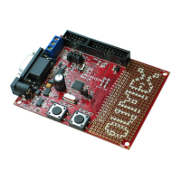
Datasheet of LPC-P11C24 - DEV BOARD FOR LPC11C24 CORTEX M0
Contact us: sales@integrated-circuit.com Website: www.integrated-circuit.com
OLIMEX© 2012 LPC-P11C24 user's manual
1.3 Organization
Each section in this document covers a separate topic, organized as follows:
– Chapter 1 is an overview of the board usage and features
– Chapter 2 provides a guide for quickly setting up the board and software notes
– Chapter 3 contains the general board diagram and layout
– Chapter 4 describes the component that is the heart of the board: the LPC11C14
microcontroller
– Chapter 5 is an explanation of the control circuitry associated with the microcontroller to
reset. Also shows the clocks on the board
– Chapter 6 covers the connector pinout, peripherals and jumper description
– Chapter 7 shows the memory map
– Chapter 8 provides the schematics
– Chapter 9 contains the revision history, useful links and support information
Page 6 of 26