Distributor of Olimex LTD: Excellent Integrated System Limited
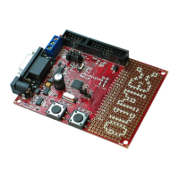
Datasheet of LPC-P11C24 - DEV BOARD FOR LPC11C24 CORTEX M0
Contact us: sales@integrated-circuit.com Website: www.integrated-circuit.com
OLIMEX© 2012 LPC-P11C24 user's manual
2.3 Powering the board
The board is powered via the PWR jack by 7 to 9 volts (preferably closer to the upper limit if you
use all peripherals and GPIOs).
When powered by 9V the current measured is around 40mA. The red, green and yellow leds (PWR
LED, LED1 and LED2) turn on.
2.4 Prebuilt software and bootloader
The prebuilt software is a bootloader and a simple LEDs and buttons test. When you power the
board initially all LEDs will be on. If you press and hold the B1 button LED2 should start blinking.
If you press and hold WAKE_UP button LED1 should start blinking. Upon releasing the buttons the
LEDs should return to their initial “always on” state.
In order to connect with the bootloader you should close PIO1_RS and RST_E jumpers. You will
also need RS232 cable and RS232 computer port. After that you can use NXP's FlashMagic
software to check if the board is connected successfully. You can also load binary files via the
RS232 using the FlashMagic.
Page 8 of 26