25
ASSEMBLY
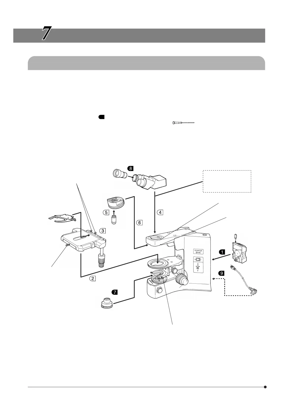
7-1 Assembly Diagram
The diagram below shows the sequence of assembly of the various modules. The numbers indicate the order of
assembly.
The module numbers shown in the following diagram are merely the typical examples. For the modules with which the
module numbers are not given, please consult your Olympus representative or the catalogues.
# When assembling the microscope, make sure that all parts are free of dust and dirt, and avoid scratching any
parts or touching glass surfaces.
Assembly steps enclosed in will be detailed on the subsequent pages.
}All assembly operations are possible by using the Allen screwdriver ( ) provided with the microscope.
Eyepiece
WHN10X (FN 22)
WHN10X-H (FN 22)
35WHN10X (FN 22)
SWH10X-H (FN 26.5)
35SWH10X (FN 26.5)
Observation tube
U-BI30-2 (FN 22)
U-TR30-2 (FN 22)
U-TBI3 (FN 22)
U-SWTR-3 (FN 26.5)
U-ETBI (FN 22)
U-TTBI (FN 22)
Intermediate attachment
U-EPA2
U-DO3
BX-URA2, etc.
Tube clamping screw
Revolving nosepiece
U-5RE-2
U-D6RE
Slide holder clamping knobs
Slide holder
U-HLDT-4
U-HRDT-4
U-HLST-4
UIS2/UIS
series
objective
Stage
U-SVRB-4
U-SVLB-4
U-SRG
Stage clamping
knob
Condenser
U-AC2
U-SC3
U-AAC
Halogen bulb
6V30WHAL
Lamp
socket
U-LS30-4
Power cord
Microscope frame
BX41TF
Condenser clamping knob
Revolving nosepiece
clamping screw